
Apparatus for reducing polymer deposition on a substrate and substrate support

a technology of substrate and support, applied in the direction of cable/conductor manufacturing, insulation conductor/cable, coating, etc., can solve the problems of unwanted polymer deposition on the surface of the chamber, adversely affecting the wafer itself, and aggressive oxygen cleaning of the processing chamber

Inactive Publication Date: 2007-08-07
LAM RES CORP
View PDF47 Cites 54 Cited by
  • Summary
  • Abstract
  • Description
  • Claims
  • Application Information

AI Technical Summary

Benefits of technology

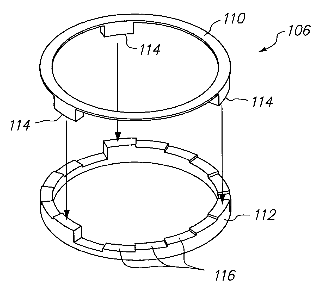
[0015]In accordance with another aspect of the invention the plasma processing apparatus comprises a processing chamber, a process gas which energizes process gas in an interior of the processing chamber into a plasma state for processing a substrate, a substrate support which supports a substrate within the interior of the processing chamber, the substrate support having an upper surface, an upper ring surrounding the substrate support, the upper ring having a portion extending under a substrate when the substrate is located on the substrate support, and a coupling ring surrounding the substrate support, the coupling ring having a first ring rotatable with respect to a second ring to adjust height of the coupling ring and adjust a gap between the upper ring and the substrate.

Problems solved by technology

During processing of substrates, unwanted polymer deposition on the surfaces of the chamber can occur.
This buildup may cause problems if it flakes off and is carried onto the top surface of the electrostatic chuck.
The contaminants can also be deposited on and adversely affect the wafer itself.
The aggressive oxygen cleaning of the processing chamber is undesirable because it adds to the wafer cycle time, reducing through-put of the system.
In addition, the aggressive oxygen clean will shorten the lives of members within the processing chamber due to ion bombardment of these members.
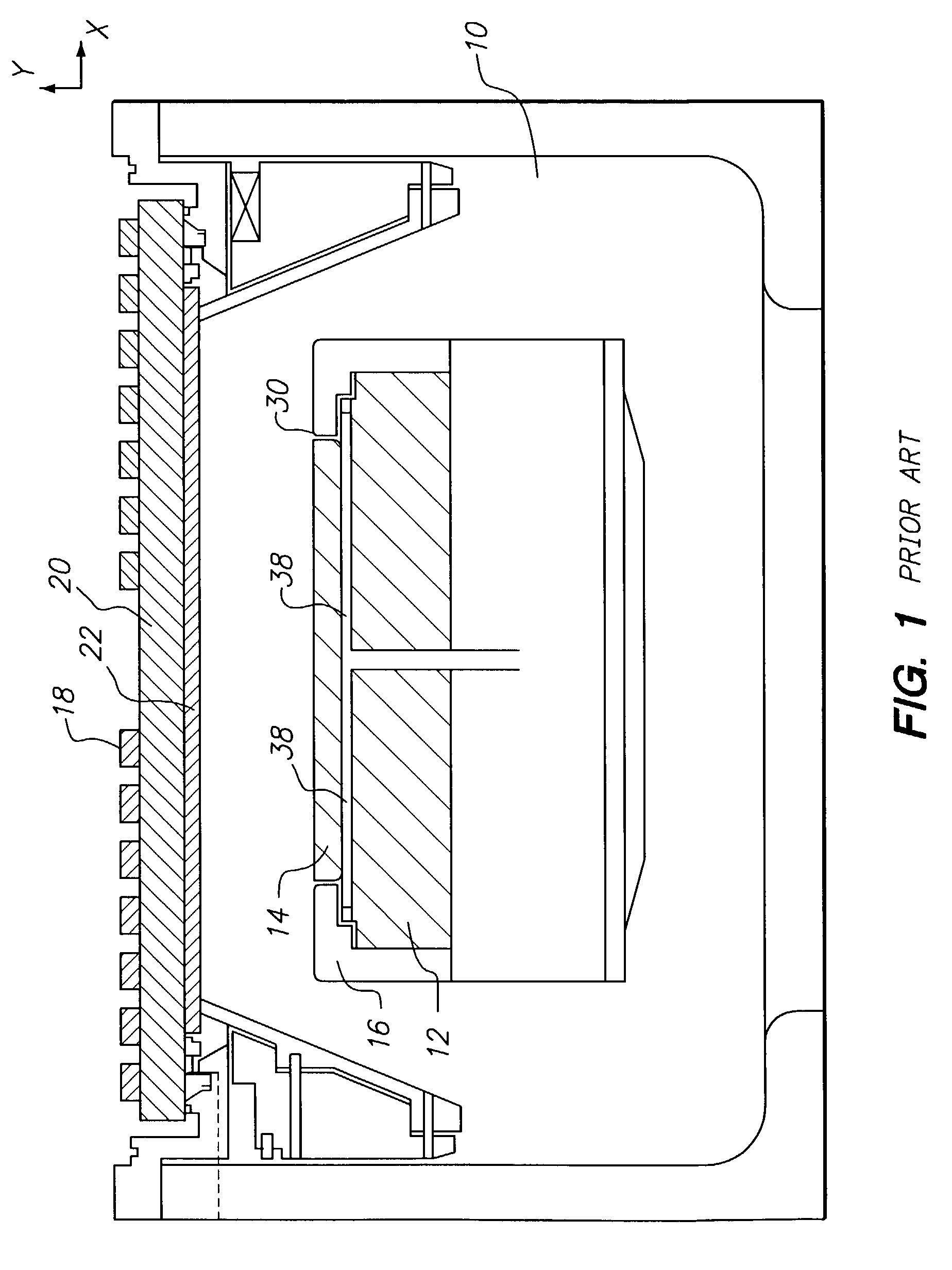
However, process gas and volatile byproducts within the chamber 10 may migrate into the gap 30 and cause undesirable polymer deposits in the gap and on the underside edge of the wafer which may flake off and cause contamination of the wafer and / or chamber.
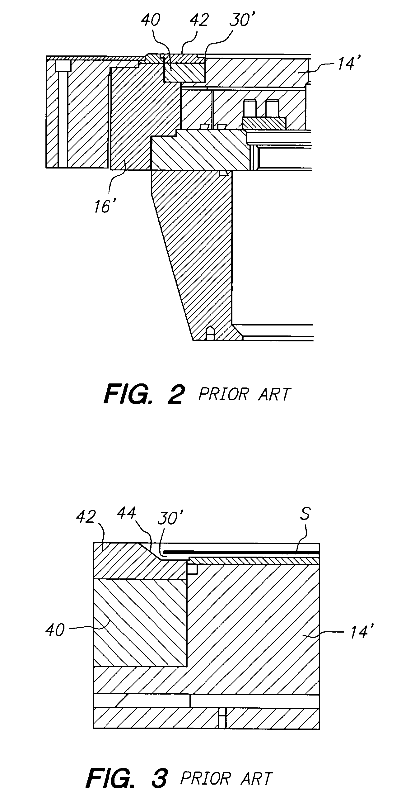
However, this additional vertical clearance gap 30′ provides additional opportunity for polymer buildup which may flake off and contaminate the substrate S or the electrostatic chuck 14′.

Method used


Image

  • Apparatus for reducing polymer deposition on a substrate and substrate support
  • Apparatus for reducing polymer deposition on a substrate and substrate support
  • Apparatus for reducing polymer deposition on a substrate and substrate support

Examples


Embodiment Construction

[0024]A portion of a substrate support for a vacuum processing chamber according to one embodiment of the present invention is illustrated in FIG. 4. The substrate support 100 illustrated in FIG. 1 includes an electrostatic chuck 102, a focus ring 104, a coupling ring 106, and a hot edge ring 108.

[0025]As is well known to those familiar with the plasma processing art, the rings surrounding the electrostatic chuck including the focus ring 104, coupling ring 106, and hot edge ring 108 help focus the ions from the RF induced plasma region on the surface of the substrate to improve process uniformity, particularly at the edge of the substrate. This is because when RF power is supplied to substrate holding chuck 102, equipotential field lines are set up over substrate and bottom electrode. These field lines are not static but change during the RF cycle. The time averaged field results in the bulk plasma being positive and the surface of the substrate and electrostatic chuck negative. Due...


PUM

PropertyMeasurementUnit
heightaaaaaaaaaa
pressureaaaaaaaaaa
pressureaaaaaaaaaa

Abstract

An adjustable RF coupling ring is capable of reducing a vertical gap between a substrate and a hot edge ring in a vacuum processing chamber. The reduction of the gap reduces polymer deposits on the substrate and electrostatic chuck and improves wafer processing.

Description

FIELD OF THE INVENTION[0001]The invention relates to an apparatus and method for reducing polymer deposition on a substrate and substrate support, and more particularly, the invention relates to the adjustment of a gap between a substrate holder and a substrate to reduce polymer deposition on exposed surfaces of the substrate holder and bottom surfaces of the substrate.DESCRIPTION OF THE RELATED ART[0002]Vacuum processing chambers are generally used for chemical vapor depositing (CVD) and etching of materials on substrates by supplying process gas to the vacuum chamber and application of an RF field to the gas. Examples of parallel plate, inductively coupled plasma (TCP™, also called ICP), and electron-cyclotron resonance (ECR) reactors are disclosed in commonly owned U.S. Pat. Nos. 4,340,462; 4,948,458; and 5,200,232. The substrates are held in place within the vacuum chamber during processing by substrate holders. Conventional substrate holders include mechanical clamps and electr...

Claims


Application Information

Patent Timeline
Patent Type & Authority Patents(United States)
IPC IPC(8): H01L21/00C23C16/00H01J37/32
CPCH01J37/32623H01L21/67069H01J37/32642Y10S156/915H01J37/32
Inventor TONG, JOSELENZ, ERIC H
Owner LAM RES CORP
Learn More