
DC-DC converter and error amplifier thereof

a technology of error amplifier and converter, which is applied in the direction of dc-dc conversion, power conversion system, instruments, etc., can solve the problems of limiting the response time of error amplifier and the stabilization time of dc-dc converter, capacitors that cannot be integrated in chips, and more power consumption, so as to achieve fast stabilization, low power consumption, and fast response

Active Publication Date: 2007-08-07
IND TECH RES INST
View PDF6 Cites 31 Cited by
  • Summary
  • Abstract
  • Description
  • Claims
  • Application Information

AI Technical Summary

Benefits of technology

[0008]The invention provides novel error amplifiers with fast response and low power consumption. The compensation capacitor required by the error amplifier is low and can be integrated in a chip. Utilizing the error amplifier, the invention provides DC-DC converters having fast stabilization.

Problems solved by technology

The compensation capacitor, however, limits the response time of the error amplifier and the stabilization time of the DC-DC converter.
The compensation capacitor is too large to be integrated in a chip, and thus connecting wires between the external compensation capacitor and the chips resultingly act as parasitic capacitors and resistors.
However, the large charge / discharge current results in more power consumption.

Method used


Image

  • DC-DC converter and error amplifier thereof
  • DC-DC converter and error amplifier thereof
  • DC-DC converter and error amplifier thereof

Examples


Embodiment Construction

[0027]The following description is of the best-contemplated mode of carrying out the invention. This description is made for the purpose of illustrating the general principles of the invention and should not be taken in a limiting sense. The scope of the invention is best determined by reference to the appended claims.

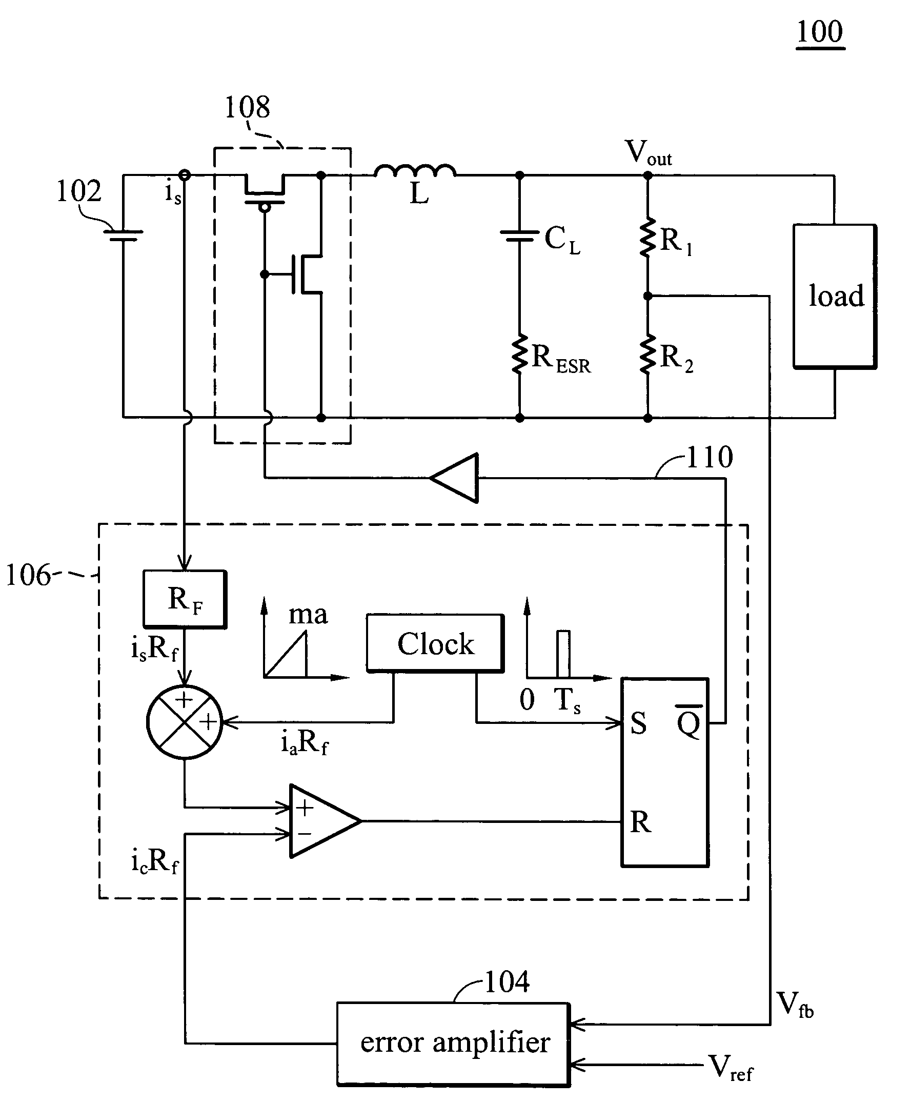
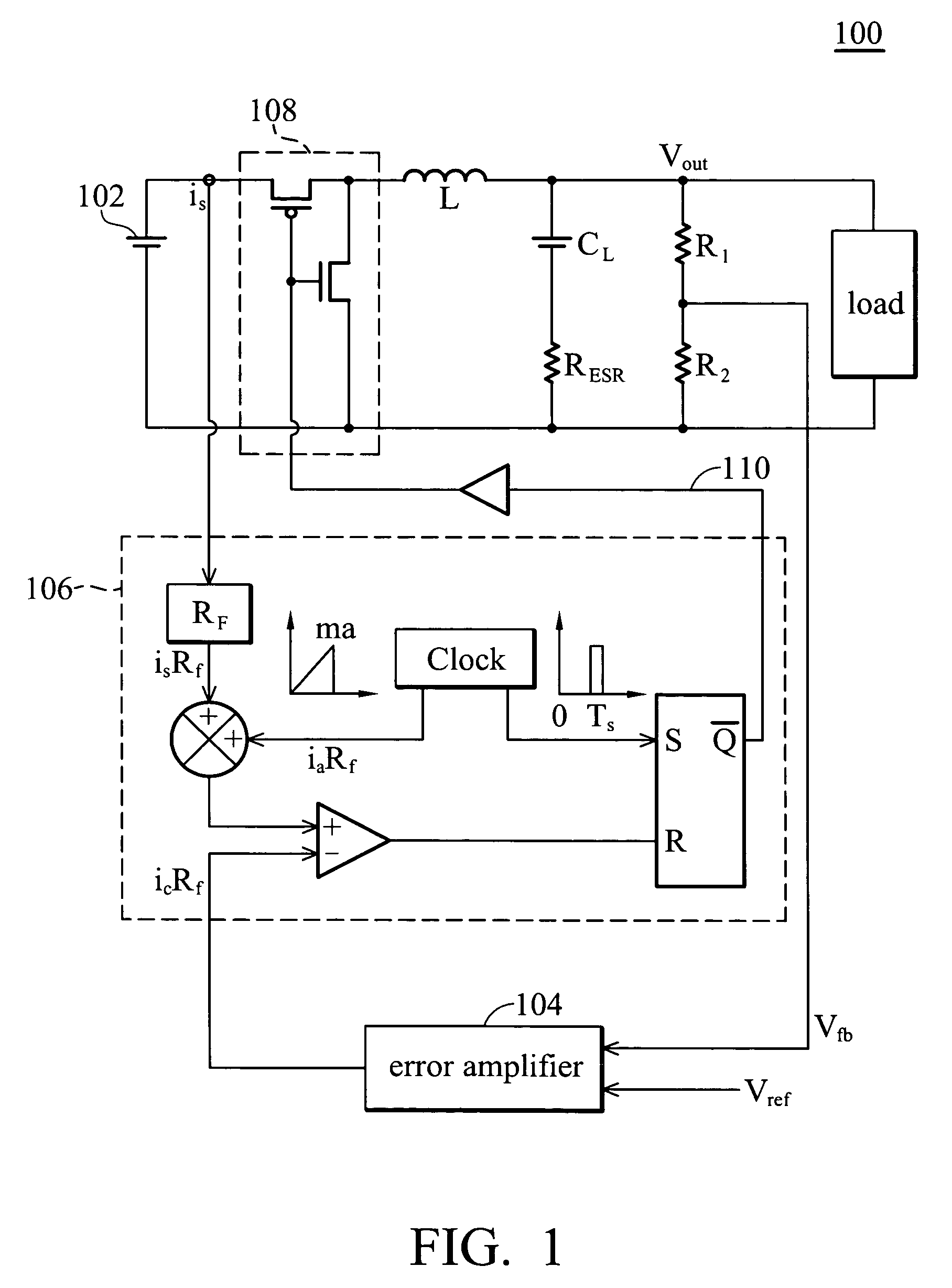
[0028]FIG. 1 shows a DC-DC converter of the invention. The DC-DC converter 100 comprises a DC voltage source 102, an output capacitor CL, an error amplifier 104, a pulse generator 106 (such as a PWM), and a power stage circuit 108. The DC-DC converter converts the output voltage of the DC voltage source 102 to a voltage level suitable for portable electronic devices. The output voltage of the DC-DC converter 100 is Vout. When the load of the DC-DC converter requires more current, the electrical charge of the output capacitor CL is injected into the load. The output voltage Vout, therefore, decreases. The output of the error amplifier 104 varies with the voltage differe...


PUM


Abstract

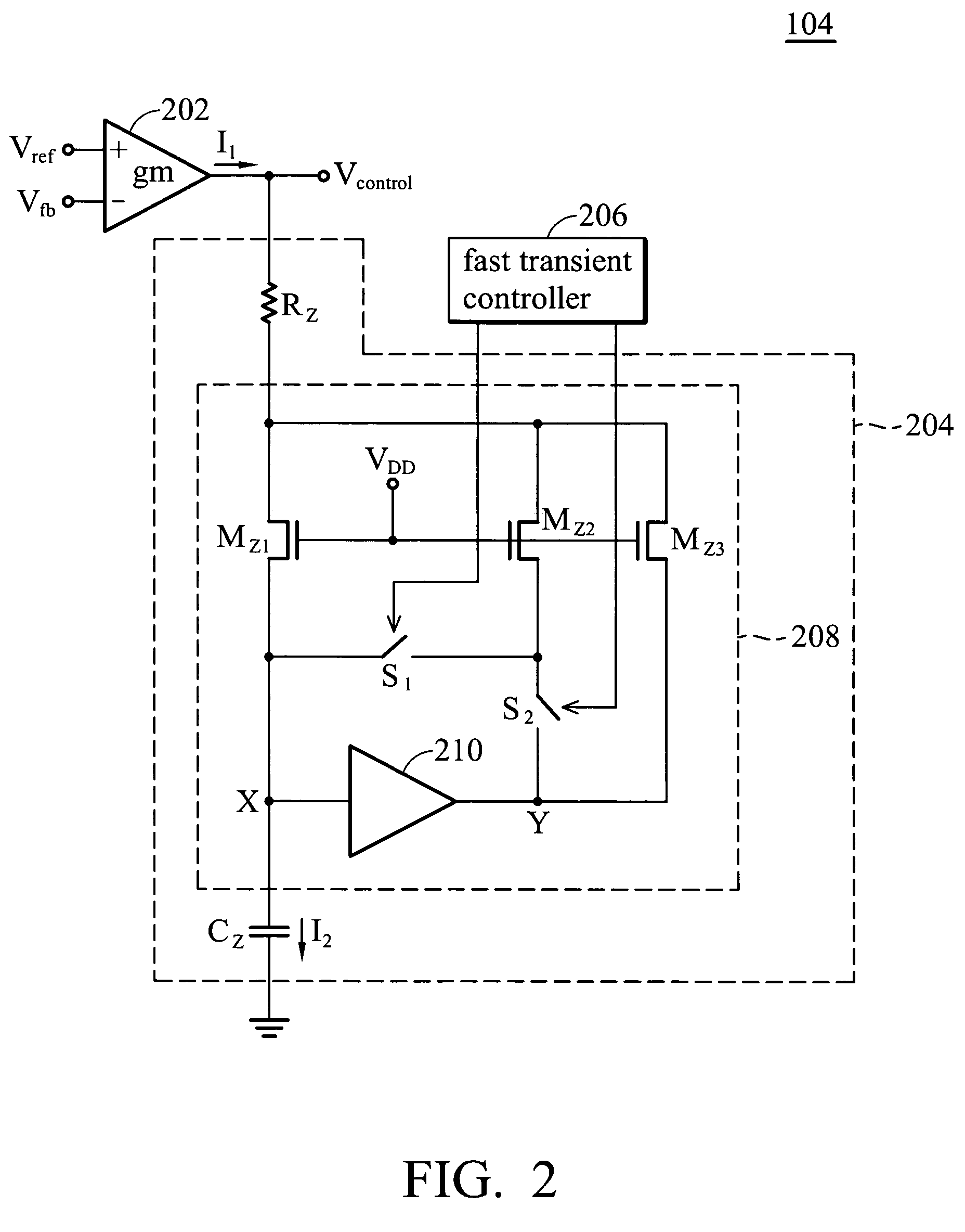
A DC-DC converter includes an error amplifier that includes an operational transconductance amplifier (OTA), a compensation circuit, and a fast transient controller. The OTA includes a compensation resistor, a compensation capacitor of Cz, and a Miller circuit. The equalization capacitance generated by the compensation capacitor and the Miller circuit is (1+k) Cz. The Miller circuit includes three transistors operated in the triode region. The ratio of the current through the transistors is 1:mk:(1−m)k. The current through the compensation capacitor in a second mode is (1+mk) times that in a first mode. The fast transient controller switches the Miller circuit between the first and second modes according to a feedback voltage dependent on the output voltage of the DC-DC converter.

Description

BACKGROUND OF THE INVENTION[0001]1. Field of the Invention[0002]The invention relates to DC-DC converters and error amplifiers thereof.[0003]2. Description of the Related Art[0004]Portable electronic devices, such as mobile phones, personal digital assistants, and portable multimedia entertainment players, are powered by batteries. A DC-DC converter is required to convert the battery voltage to the required voltage level.[0005]The DC-DC converter comprises an error amplifier, which requires a large compensation capacitor. The compensation capacitor, however, limits the response time of the error amplifier and the stabilization time of the DC-DC converter. The compensation capacitor is too large to be integrated in a chip, and thus connecting wires between the external compensation capacitor and the chips resultingly act as parasitic capacitors and resistors.[0006]In another conventional DC-DC converter, the compensation capacitor is charged or discharged by a large current provided ...

Claims


Application Information

Patent Timeline
IPC IPC(8): G05F1/613
CPCH02M3/158
Inventor CHEN, KE-HORNGHUANG, LI-RENHUANG, HONG-WEIKUO, SY-YEN
Owner IND TECH RES INST
Learn More