RF MEMS switch with spring-loaded latching mechanism

a technology of latching mechanism and micro-fabricated electromechanical switch, which is applied in the field of micro-fabricated electromechanical switch having a spring-loaded latching mechanism, can solve the problems of increasing the cost of the switch, the switch is bigger and/or heavier than desired, and the latching cannot be in multiple states

Active Publication Date: 2007-08-07
HRL LAB
View PDF10 Cites 23 Cited by
  • Summary
  • Abstract
  • Description
  • Claims
  • Application Information

AI Technical Summary

Benefits of technology

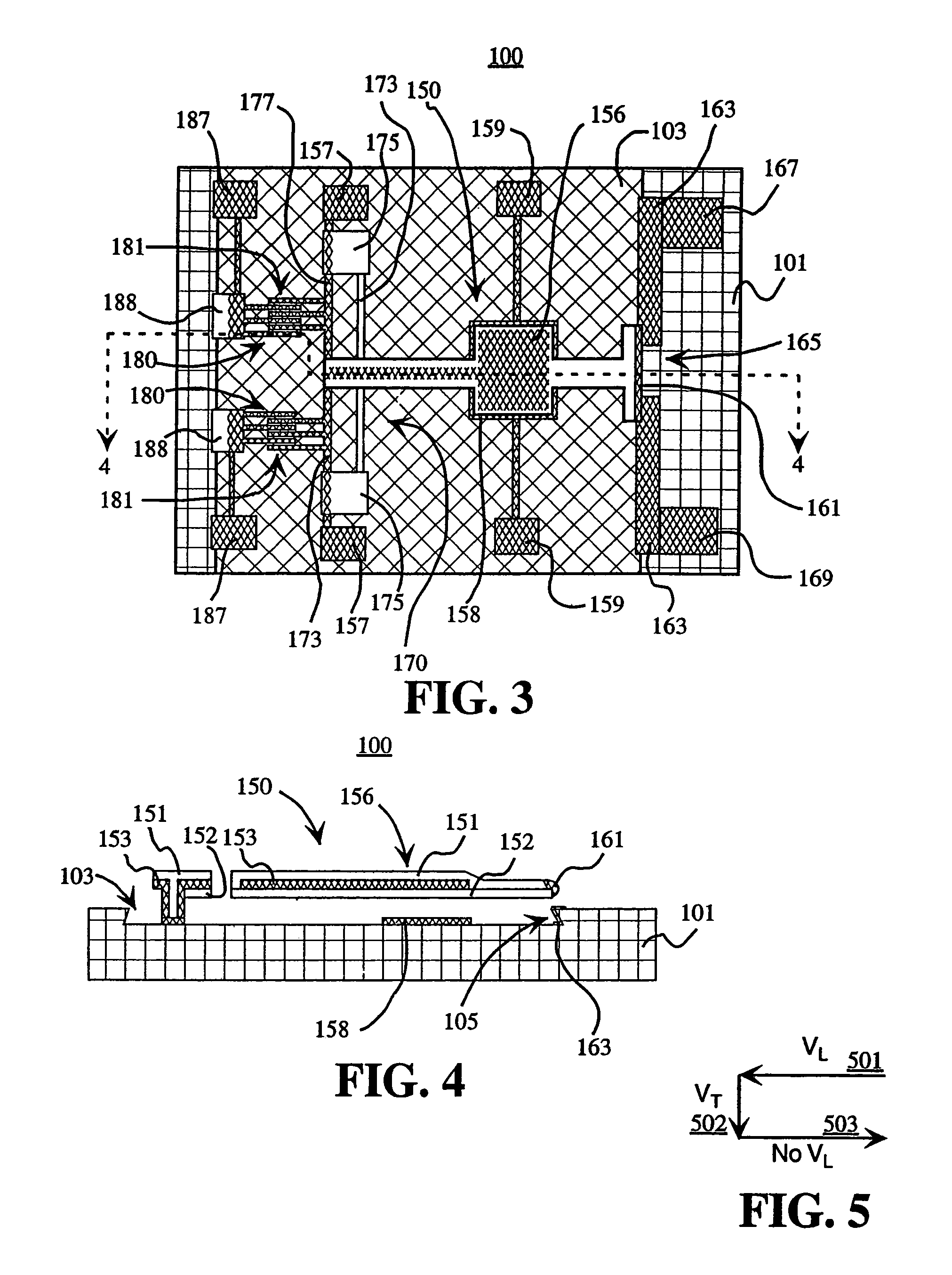
[0015]According to some embodiments of the present invention, movement in orthogonal directions may be provided by a combined comb-drive actuator structure and parallel plate actuator structure to move a cantilever arm prior to latching or unlatching. The comb-dri...

Problems solved by technology

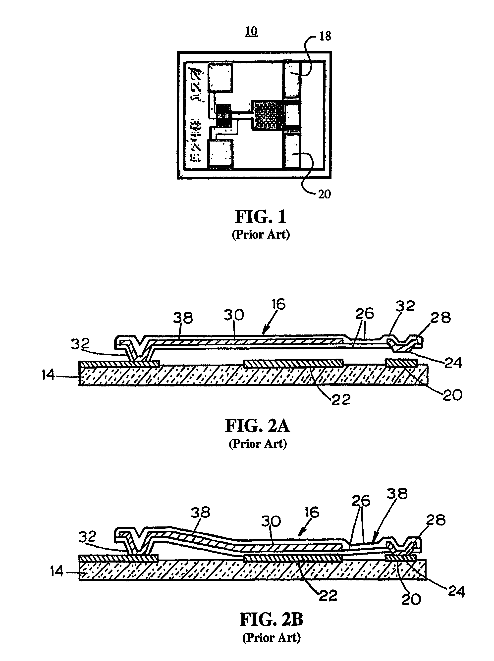
However, most of the applications listed above would benefit from size and weight reduction since the mechanical latching switches currently in use tend to be larger and heavier than desired.
Semiconductor switches, such as made using PIN diodes and FET switches, are small, but they typically cannot latch in multiple states without a constant energy ...

Method used


Image

  • RF MEMS switch with spring-loaded latching mechanism
  • RF MEMS switch with spring-loaded latching mechanism
  • RF MEMS switch with spring-loaded latching mechanism

Examples


Embodiment Construction

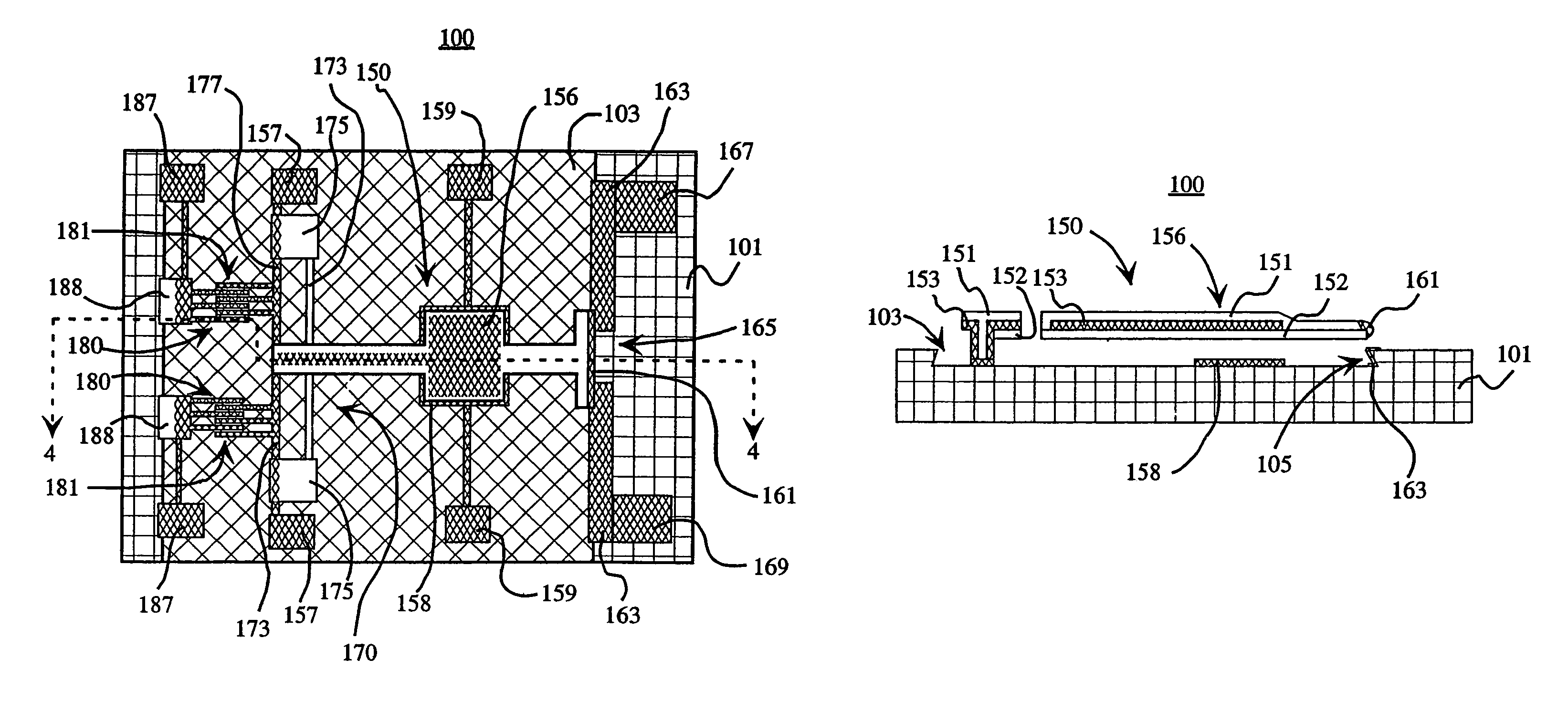
[0027]It should be appreciated that the particular embodiments shown and described herein are examples of the invention and are not intended to otherwise limit the scope of the present invention in any way. Indeed, for the sake of brevity, conventional electronics, manufacturing, MEMS technologies and other functional aspects of the systems (and components of the individual operating components of the systems) may not be described in detail herein. Furthermore, for purposes of brevity, embodiments of the invention are frequently described herein as pertaining to a micro electromechanical switch for use in electrical or electronic systems. It should be appreciated that many other manufacturing techniques could be used to create the embodiments described herein. Further, the embodiments according to the present invention would be suitable for application in electrical systems, optical systems, consumer electronics, industrial electronics, wireless systems, space applications, or any o...


PUM

PropertyMeasurementUnit
Electrical conductoraaaaaaaaaa
Electric potential / voltageaaaaaaaaaa
Electrostatic attractive forceaaaaaaaaaa

Abstract

Apparatus for a micro-electro-mechanical switch that provides for latching switching action. The switch has a cantilever arm disposed on a substrate that can be moved in orthogonal directions for latching and unlatching. To latch the switch, the cantilever arm is moved back by a comb-drive actuator and then pulled down by electrodes disposed on the substrate and the cantilever arm. The comb-drive actuator switch is then released and the cantilever arm moves forward to be captured by a dove-tail structure on the substrate. When the voltage to the electrodes on the substrate and the cantilever arm is removed, the cantilever arm is held in place by the dove-tail structure. The switch is unlatched by actuating the comb-drive actuator to move the cantilever arm away from the dove-tail structure. The cantilever arm will then pop up once it is released from the dove-tail structure.

Description

BACKGROUND[0001]1. Technical Field[0002]The present disclosure relates generally to switches. More particularly, this disclosure relates to microfabricated electromechanical switches having a spring-loaded latching mechanism.[0003]2. Description of Related Art[0004]Switch networks are found in many systems application. For example, in satellite systems, switch networks are essential for routing matrices and redundancy systems. Future satellite systems will not only require larger switch routing networks, but also increased functionality for network-centric operations. These new capabilities will includes spacecraft reconfiguration for beam switching, beam shaping, and frequency agility. Thus, it is expected that satellites will require an increasing number of switches in their payloads.[0005]In many cases, these switches need to be latching, that is, once they are actuated they will remain in a desired state even after the actuation energy source is removed. Some of the applications...

Claims


Application Information

Patent Timeline
IPC IPC(8): H01H51/22
CPCH01H59/0009H01H2001/0068Y10T29/49204Y10T29/49155Y10T29/49117Y10T29/49105
Inventor CHANG, DAVID T.SCHAFFNER, JAMES H.HSU, TSUNG-YUANSCHMITZ, ADELE E.
Owner HRL LAB
Why Eureka
Try Eureka