
Gimbal optical system for document image capture

Inactive Publication Date: 2007-08-07
HEWLETT PACKARD DEV CO LP
View PDF3 Cites 6 Cited by
  • Summary
  • Abstract
  • Description
  • Claims
  • Application Information

AI Technical Summary

Benefits of technology

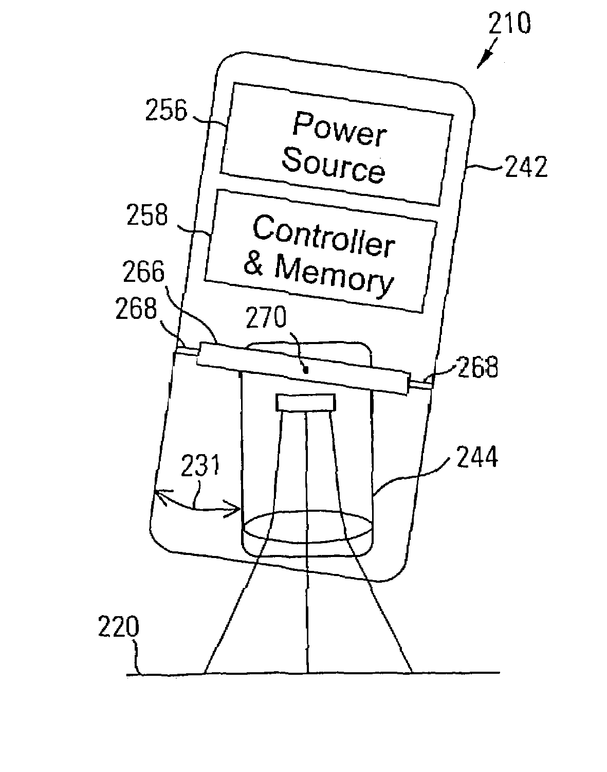
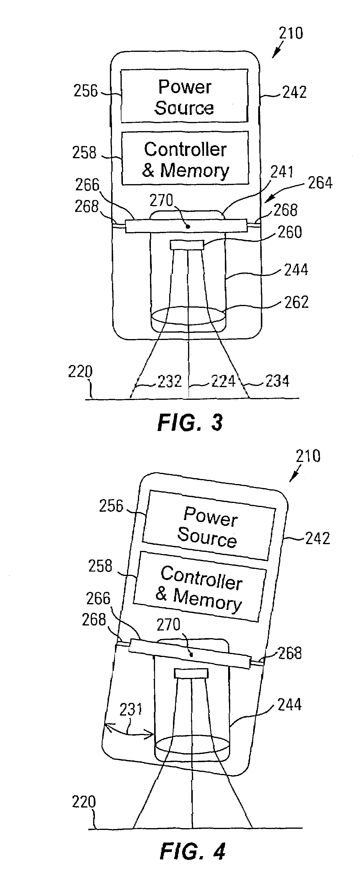
[0013]To assist in achieving the aforementioned needs, the inventor has devised an electronic imaging device having an optical assembly pivotally mounted therein. The pivot mount allows the optical assembly to be pulled by gravity into a vertical orientation over a document. This improves image quality by aligning the optical axis of the optical assembly perpendicularly with respect to the document, preventing image distortion.

Problems solved by technology

Portable imaging devices of the type described above are not without their problems.
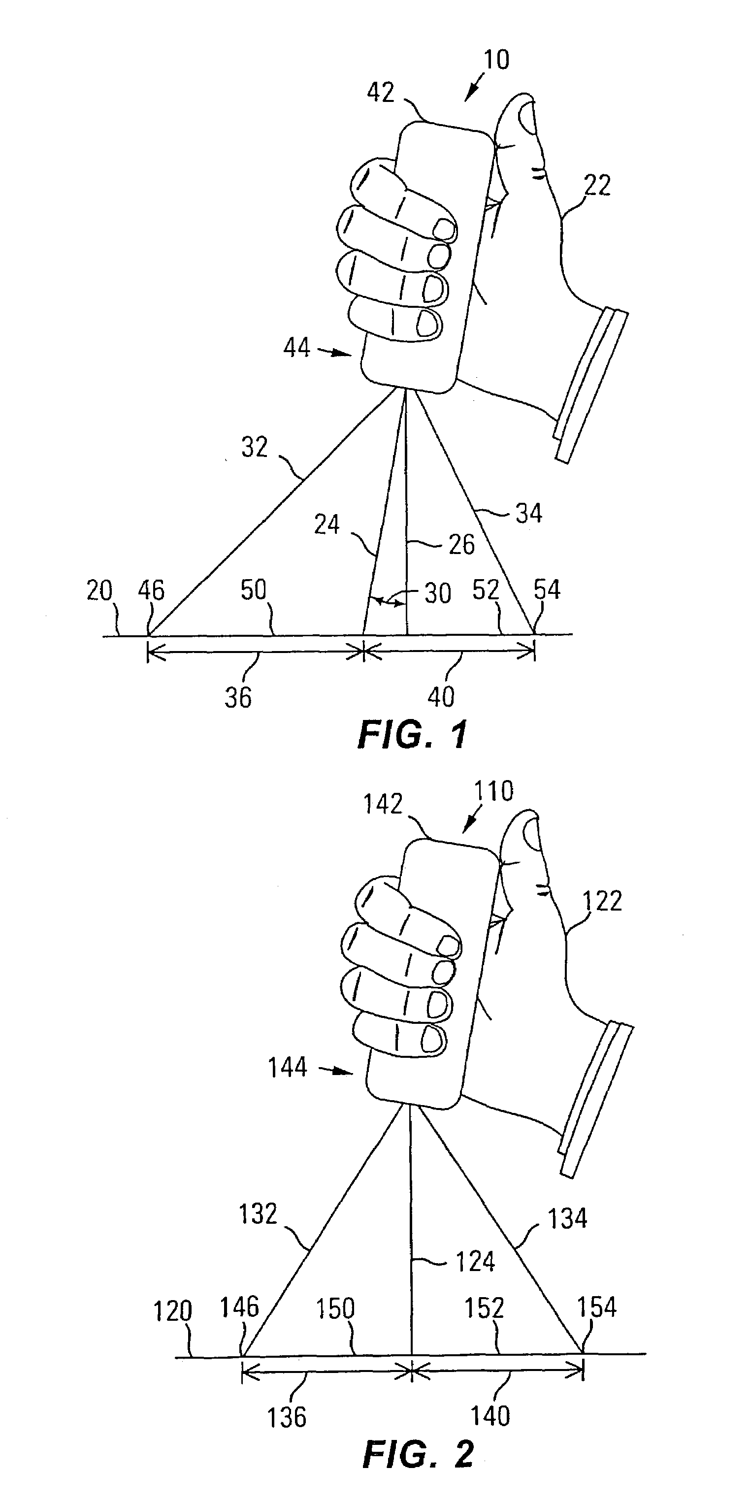
For example, when a portable imaging device is positioned over a document, it is difficult, if not impossible, to perfectly orient the imaging device by hand so that the optical axis is perpendicular to the document.
However, as portable scanners become smaller, their bases become increasingly narrow and correct orientation becomes more difficult.
If the imaging device is not held with the optical axis perpendicular to the document face, the resulting image of the document will be stretched and may be blurry and illegible.
However, it is difficult to properly orient a digital camera even when held in such a fixture if the fixture allows for angular adjustment, as most common tripods do.
Some tripods include an air bubble tilt meter, but bubble meters are not very accurate and offer no feedback for large angles when the bubble moves beyond the viewable window.
Furthermore, the usefulness and portability of a digital camera requiring a tripod or fixture for document imaging is greatly limited.

Method used


Image

  • Gimbal optical system for document image capture
  • Gimbal optical system for document image capture
  • Gimbal optical system for document image capture

Examples


Embodiment Construction

[0034]An electronic imaging device 10 may be used to detect and store the image of an object in electrical form. Typical types of electronic imaging devices include digital cameras and scanners. As digital cameras and scanners have become more portable and computers have become more widely used, document imaging has developed into a very useful tool. A document 20 which may contain both text and graphics may be electronically photographed or scanned, and the resulting image transferred to a computer, manipulated, combined with other documents or information, and printed or transferred across networks to computers across the world. Text contained in an electronic image can also be converted from graphical form to a text file by optical character recognition (OCR) software, allowing the text to be easily edited or manipulated.

[0035]Flat bed image scanners may be used to easily scan an entire document in one pass, but are typically large, desk bound machines which are not easily portab...


PUM


Abstract

An imaging device for document imaging may comprise a housing and an optical system having a lens system and an optical detector. The optical system is responsive to image light reflected by an object and produces image data representative of the image light. The optical system is pivotally mounted to said housing and is biased toward a vertical orientation inside said housing by gravity.

Description

CROSS REFERENCE TO RELATED APPLICATION[0001]This is a continuation of application Ser. No. 09 / 311,527 filed on May 13, 1999, which is hereby incorporated by reference herein.FIELD OF THE INVENTION[0002]The present invention relates generally to the field of document imaging, and more particularly, to a system and method for vertically orienting an optical path in a digital camera.BACKGROUND OF THE INVENTION[0003]Imaging devices such as optical cameras and scanners are well known in the art and may be used to quickly and easily capture the image of a document for numerous applications. The images may be processed and stored either chemically on photographic paper, or electronically in the form of electrical signals, either analog or digital. As computer use becomes more prevalent, document imaging is becoming more important and widespread. In a typical digital camera or scanner application, the image data signals produced by the camera or scanner may be used by a personal computer to...

Claims


Application Information

Patent Timeline
IPC IPC(8): H04N5/225H04N1/107H04N1/195
CPCH04N1/107H04N5/2251H04N1/195H04N2201/0458H04N23/50
Inventor OLIVER, THOMAS C
Owner HEWLETT PACKARD DEV CO LP
Learn More