Non-volatile semiconductor memory device and method for reading the same
a non-volatile semiconductor and memory device technology, applied in static storage, digital storage, instruments, etc., can solve the problems of difficult to set the read reference ir to be a desired value, and the inability to achieve the optimum read conditions, etc., to achieve stably read out, high accuracy, and high accuracy.
- Summary
- Abstract
- Description
- Claims
- Application Information
AI Technical Summary
Benefits of technology
Problems solved by technology
Method used
Image
Examples
first embodiment
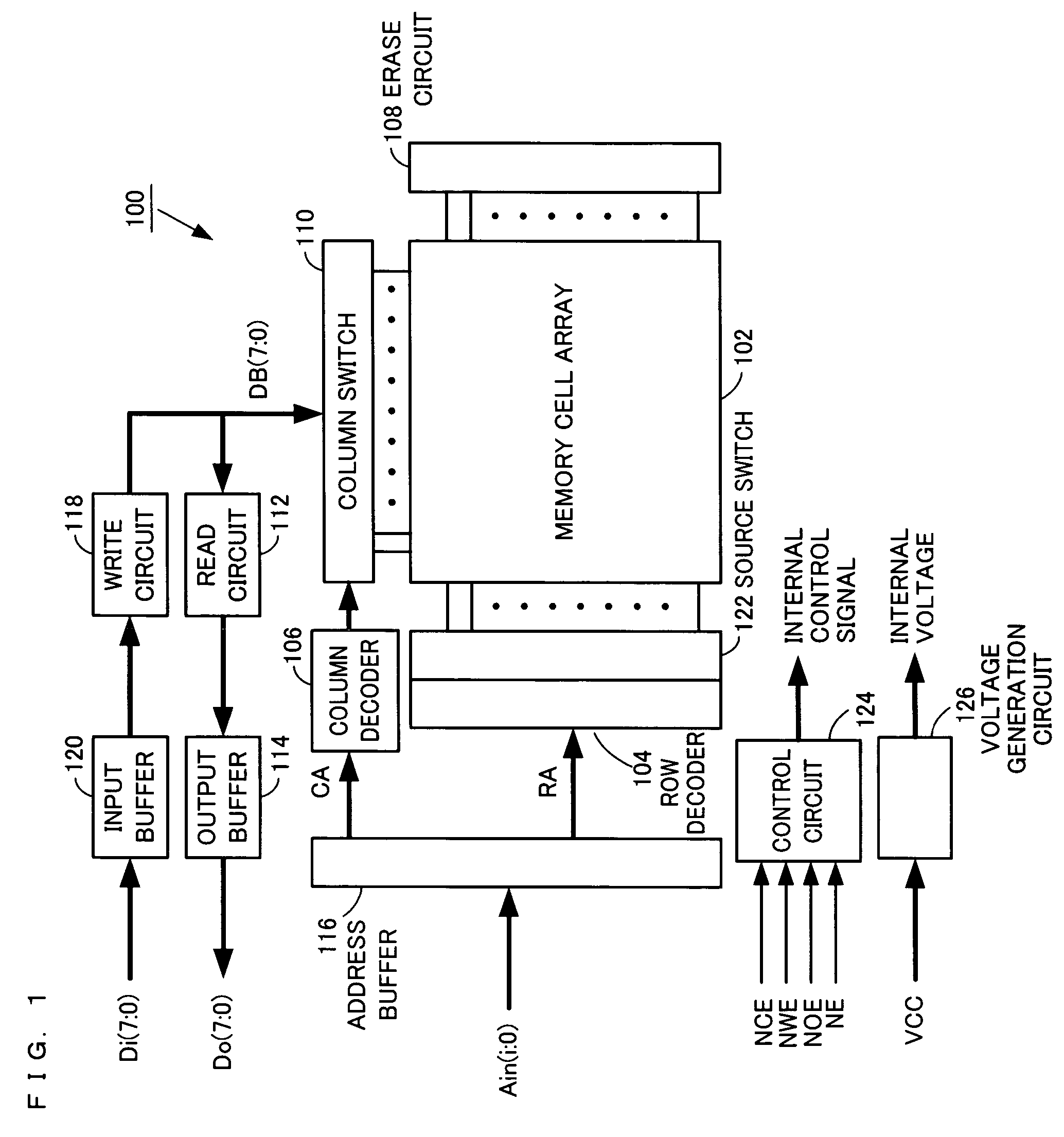
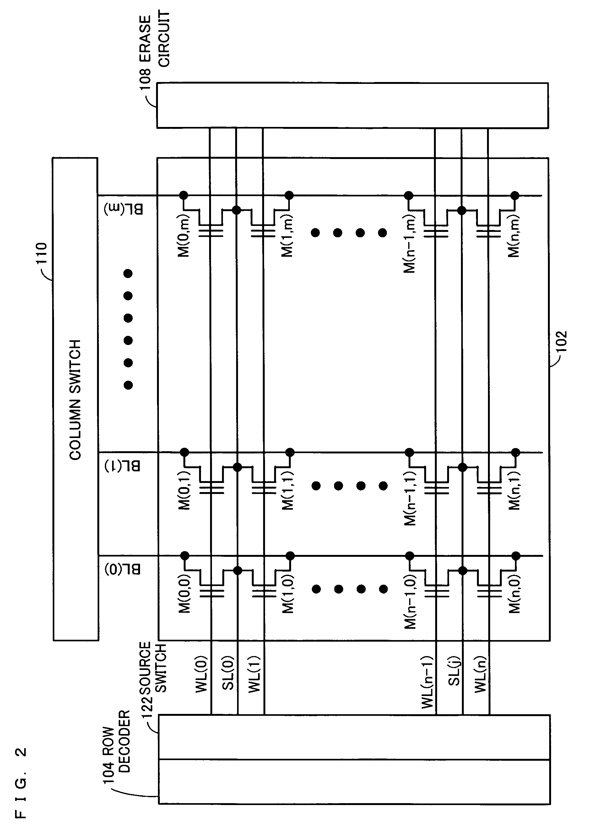
[0069]FIG. 1 is a diagram illustrating a structure of a flash EEPROM according to a first embodiment of the present invention. FIG. 2 is a diagram illustrating details of a memory cell array contained in the flash EEPROM of FIG. 1. In this and other embodiments, it is assumed that input / output data has a bit width of 8 bits in flash EEPROMs described below.
[0070]A flash EEPROM 100 of FIG. 1 comprises a memory cell array 102 for storing data. In the memory cell array 102, memory cell transistors M(0, 0) to M(n, m) having a double-gate structure are provided on corresponding intersections of word lines WL(0) to WL(n) and bit lines BL(0) to BL(m) (see FIG. 2). The control gates of memory cells provided on the same row are connected in common to a corresponding one of the word lines WL(0) to WL(n). The drains of memory cells provided on the same column are connected in common to a corresponding one of the bit lines BL(0) to BL(m). Two opposing sources of a pair of memory cells provided ...
second embodiment
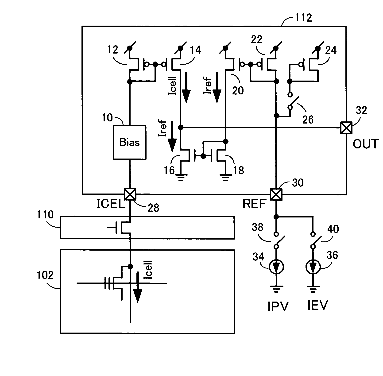
[0095]In a second embodiment, a flash EEPROM capable of setting a read reference with higher accuracy will be described. In the first embodiment, a method of setting a read reference using two current sources will be described. In general, a current source used in the first embodiment is composed of a transistor other than a double-gate structure transistor for use in a memory cell transistor, and a diode, a resistor, and the like. The reason is the following. If a double-gate structure transistor is used to construct a current source, a write operation needs to be performed with respect to a transistor contained in the current source in order to set a current flowing through the current source to be a predetermined value. However, a read reference which has been correctly set in advance is required to determine whether or not a write operation is correctly performed. Thus, there is a contradiction.
[0096]To avoid this situation, the write verification reference current IPV and the e...
third embodiment
[0111]In a third embodiment, a flash EEPROM in which a reference cell and a memory cell array are disposed side by side will be described. In the second embodiment, a flash EEPROM comprising a reference cell composed of a transistor having the same structure as that of a memory cell is described. This flash EEPROM requires a circuit for supplying erase and write power sources to a reference cell. However, when a power source supply circuit specialized to a reference cell is provided, a circuit area is increased. Also, it is preferable that a read reference is provided on a block-by-block basis where each block is small, in order to further improve the accuracy of the read reference. According to the flash EEPROM of the third embodiment, such a problem can be solved.
[0112]FIG. 11 is a diagram illustrating a structure of a flash EEPROM according to the third embodiment of the present invention. The flash EEPROM 300 of FIG. 11 is different from the flash EEPROM 200 of the second embodi...
PUM
 Abstract
Description
Claims
Application Information
 - R&D
- Intellectual Property
- Life Sciences
- Materials
- Tech Scout
- Unparalleled Data Quality
- Higher Quality Content
- 60% Fewer Hallucinations
Browse by: Latest US Patents, China's latest patents, Technical Efficacy Thesaurus, Application Domain, Technology Topic, Popular Technical Reports.
© 2025 PatSnap. All rights reserved.Legal|Privacy policy|Modern Slavery Act Transparency Statement|Sitemap|About US| Contact US: help@patsnap.com


