Multi-slice computer tomography system with data transfer system with reduced transfer bandwidth

a computer tomography and data transfer technology, applied in tomography, applications, instruments, etc., can solve the problems of high cost, inability to transfer such high data rates from the rotating part to the stationary part of the ct system, and the presently used data transfer devices are not fashioned for such high data rates

Active Publication Date: 2007-08-07
SIEMENS HEALTHCARE GMBH
View PDF7 Cites 24 Cited by
  • Summary
  • Abstract
  • Description
  • Claims
  • Application Information

AI Technical Summary

Benefits of technology

[0007]An object of the present invention is to provide a CT system as well as a method for the operation thereof with which the data quantities accumulating in the laminar detector units can be transferred to the stationary part without high costs.
[0009]The inventive computed tomography system has, in a known manner, a stationary part and a part rotatable around an examination axis (the z-axis) that carries at least one x-ray source, one detector unit opposite the x-ray source and a data acquisition unit connected with the detector unit. A data transfer device (for example using one or more optical or capacitive slip rings) for transfer of the measurement data acquired with the data acquisition unit to an image reconstruction device connected with the stationary part is disposed between the stationary part and the rotatable part. The inventive computer tomography system is characterized by the rotatable part having a storage unit, connected with the data acquisition unit, for buffering (caching) at least one part of the measurement data acquired with the data acquisition unit before transfer of that data. This enables operation of the CT system in which only one part of the measurement data accumulates during the measurement, i.e. during a scan or a rotation of the rotatable part, is transferred in real time to the stationary part via the data transfer device, and the remaining part is buffered (cached) in the storage unit and transferred at a later point in time.
[0013]The storage unit preferably is dimensioned such that it can maximally store at least all measurement data accumulating during one complete rotation of the rotatable part in the measurement operation of the CT system. In specific applications, a single such rotation can already be sufficient in order to acquire the complete examination region. However, naturally it is advantageous to dimension the storage unit such that it also can accommodate the maximum acquirable measurement data quantities of a number of scans. The storage unit itself is fashioned as a fast RAM storage in an embodiment of the inventive CT system. However, the storage unit preferably has two storage levels, of which the first storage level is a fast buffer storage (in particular a fast RAM storage) and the second storage level is a permanent storage. The measurement data received from the data acquisition unit are thereby initially buffered in the first storage level and then transferred to the slower permanent storage. This permanent storage prevents the loss of the already-acquired data in the event of a power interruption. The permanent storage can be designed, for example, a flash memory, a flash disk module, as a compact flash card or a similar storage card, as a shock-resistant hard drive or as an IBM micro-hard drive. The permanent storage is preferably portable as a removable module on the rotatable part, such that given a failure of the CT system it can be removed without difficulty and inserted into a suitable acquisition interface for transfer of the data to the image reconstruction unit.
[0014]The inventive CT system preferably is provided with a laminar detector unit with at least 256 detector rows (lines) for simultaneous acquisition of 256 slices as is used for implementation of volume CT. The x-ray source as well as the collimator disposed in front of it is fashioned in the same manner for simultaneous exposure of all detector rows. On the other side, the data transfer device preferably is dimensioned only for the real-time transfer to the stationary part of a fraction of the measurement data quantity accumulating in the operation of the CT system. The data transfer device of the inventive CT system can be realized cost-effectively in this manner without limiting the operation of the CT system due to the limited data transfer rate.
[0015]In an embodiment of the inventive CT system and the associated method, a data administration system for the administration of the data storage is provided that can be fashioned as an independent unit or as a part of the data acquisition unit. This data administration system selects (from the measurement data received via the data acquisition unit) the measurement data of predetermined slices that are transferred in real time via the data transfer device. The remaining data are stored in the storage unit and transferred at a later point in time. This offers the possibility of the specification of specific slices, for example each nth slice, a real-time reconstruction and representation of these selected slices can be realized in the event that this is necessary for the respective application. The remaining measurement data are transferred after the measurement data acquisition and can serve to improve the spatial resolution of the reconstructed examination region.

Problems solved by technology

However, the large number of detector rows in such a CT system leads to an enormous increase of the measurement data, accumulating per unit of time, which are acquired by the data acquisition unit and must be transmitted to the stationary image reconstruction unit.
However, the presently used data transfer devices are not fashioned for the transfer of such high data rates from the rotating part to the stationary part of the CT system.
This solution, however, occupies space within the CT gantry and the examination region that is already scarce, and incurs high costs.
Improved technologies for data transfer with high data rates (and the costs associated therewith) have not proven to be practical.

Method used


Image

  • Multi-slice computer tomography system with data transfer system with reduced transfer bandwidth
  • Multi-slice computer tomography system with data transfer system with reduced transfer bandwidth
  • Multi-slice computer tomography system with data transfer system with reduced transfer bandwidth

Examples


Embodiment Construction

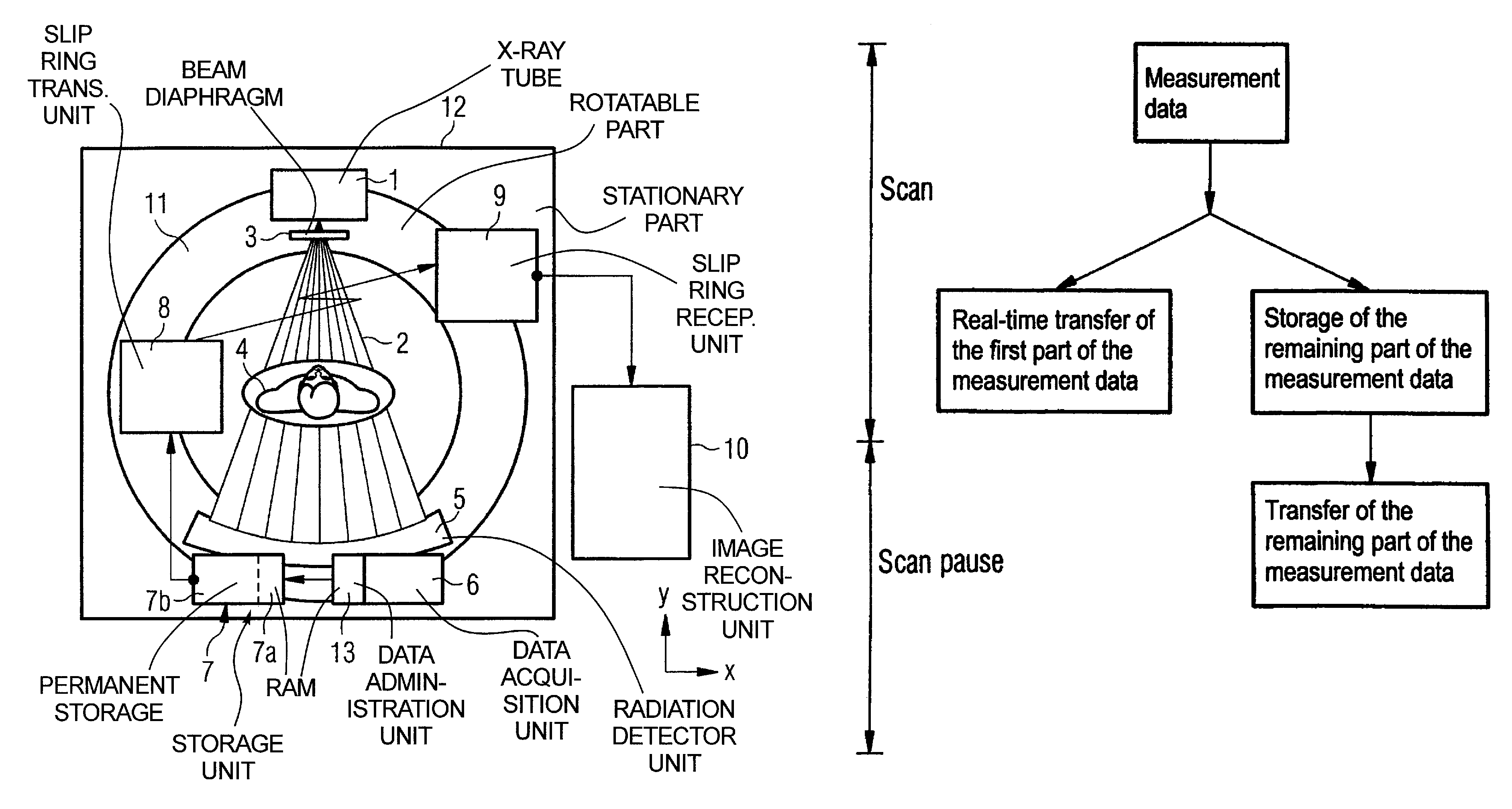
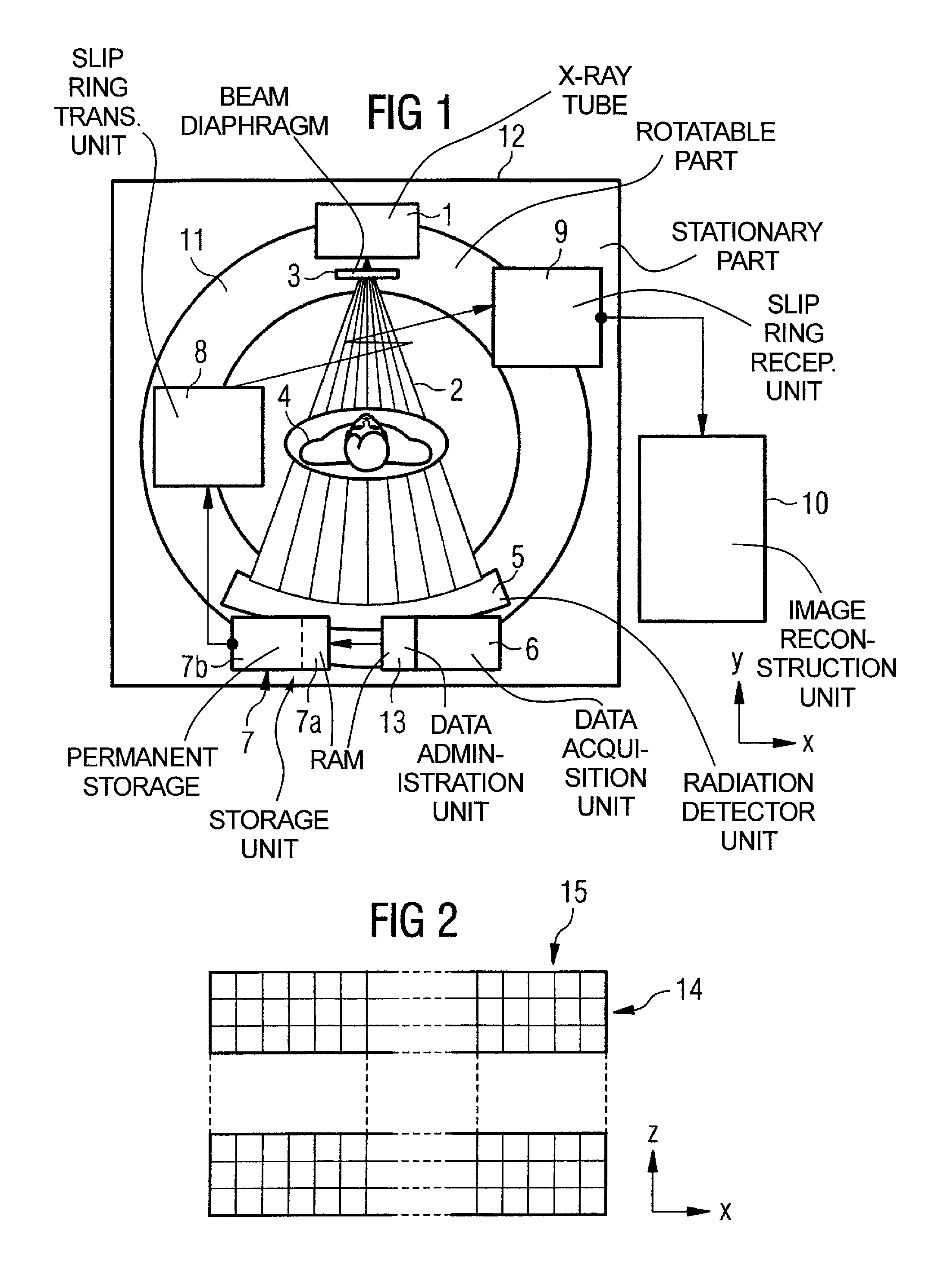
[0019]FIG. 1 schematically illustrates an example for the design of a volume CT system according to the present invention. An x-ray tube 1 attached to a rotatable part 11, known as the gantry, and emits a conical x-ray beam 2 whose aperture angle can be set in the x-direction and z-direction by a mechanically adjustable diaphragm 3. FIG. 1 shows a section perpendicular to the z-direction. The x-ray beam 2 penetrates a patient body 4 and strikes a planar detector unit 5.

[0020]In the present example, a detector unit 5 with 1024 detector rows is used with which 1024 individual slices can be acquired with a single scan. FIG. 2 schematically shows in plan view an example for the arrangement of the detector rows 14 and detector columns 15 of such a planar detector unit.

[0021]A data acquisition unit 6 disposed on the rotatable part 11 converts the analog measurement signals acquired by the detector elements of the detector unit 5 and delivers a serial stream of digital measurement data to ...


PUM

PropertyMeasurementUnit
computed tomographyaaaaaaaaaa
CTaaaaaaaaaa
specific volumeaaaaaaaaaa

Abstract

A computed tomography system has a stationary part and a part that is rotatable around an examination axis that carries at least one x-ray source, a detector unit opposite the x-ray source and a data acquisition unit connected to the detector unit. A data transfer device for transfer of measurement data (acquired with the data acquisition unit) to an image reconstruction device connected with the stationary part is disposed between the stationary part and the rotatable part. The rotatable part has a storage unit for buffering at least a part of the measurement data acquired with the data acquisition unit before their transfer. This storage unit is connected to the data acquisition unit. The computed tomography system enables operation with a high data rate without the data transfer device having to adapt to the maximal data rate.

Description

BACKGROUND OF THE INVENTION[0001]1. Field of the Invention[0002]The present invention concerns a computed tomography (CT) system of the type having a stationary part and a part rotatable around an examination axis that carries at least one x-ray source, a detector unit opposite the x-ray source and a data acquisition unit connected with the detector unit, and a data transfer device for transfer of measurement data (acquired with the data acquisition unit) to an image reconstruction device connected with the stationary part is fashioned between the stationary part and the rotatable part. The present invention also concerns a method for operation of such a CT system.[0003]2. Description of the Prior Art[0004]In multi-slice CT systems, detector arrays with a number of detector rows are used that can be simultaneously exposed by an x-ray beam that conically expands in the direction of the examination axis, what is known as the z-axis. In this manner, a number of slices of the examinatio...

Claims


Application Information

Patent Timeline
Patent Type & Authority Patents(United States)
IPC IPC(8): G01N23/083A61B6/00A61B6/03G01N23/00G01N23/06G21K1/12H04N1/21H05G1/60
CPCA61B6/032
Inventor POPESCU, STEFAN
Owner SIEMENS HEALTHCARE GMBH
Why Eureka
Try Eureka