Method and apparatus for cooling with coolant at a subambient pressure

a subambient pressure and cooling method technology, applied in the field of cooling techniques, can solve the problems of substantial heat dissipation without the use of compressors, and achieve the effects of avoiding large vapor lines, substantial heat dissipation, and freeing valuable space on the ship

Active Publication Date: 2007-08-14
RAYTHEON CO
View PDF87 Cites 55 Cited by
  • Summary
  • Abstract
  • Description
  • Claims
  • Application Information

AI Technical Summary

Benefits of technology

[0007]Some embodiments of the invention may provide numerous technical advantages. Other embodiments may realize some, none, or all of these advantages. For example, according to one embodiment, the temperature of a plurality of heat-generating devices on a ship, such as phase array antennas, may be maintained at a desired temperature through a subambient cooling system that sinks the generated heat to the body of water through an intermediary cooling loop. Such an approach can in some embodiments result in substantial heat dissipation without use of compressors. The avoidance of the use of compressors frees up valuable space on the ship. Further, in some embodiments, large vapor lines can be avoided.

Problems solved by technology

Such an approach can in some embodiments result in substantial heat dissipation without use of compressors.

Method used


Image

  • Method and apparatus for cooling with coolant at a subambient pressure
  • Method and apparatus for cooling with coolant at a subambient pressure
  • Method and apparatus for cooling with coolant at a subambient pressure

Examples


Embodiment Construction

[0012]Example embodiments of the present invention and their advantages are best understood by referring to FIGS. 1-2 of the drawings, like numerals being used for like and corresponding parts of the various drawings.

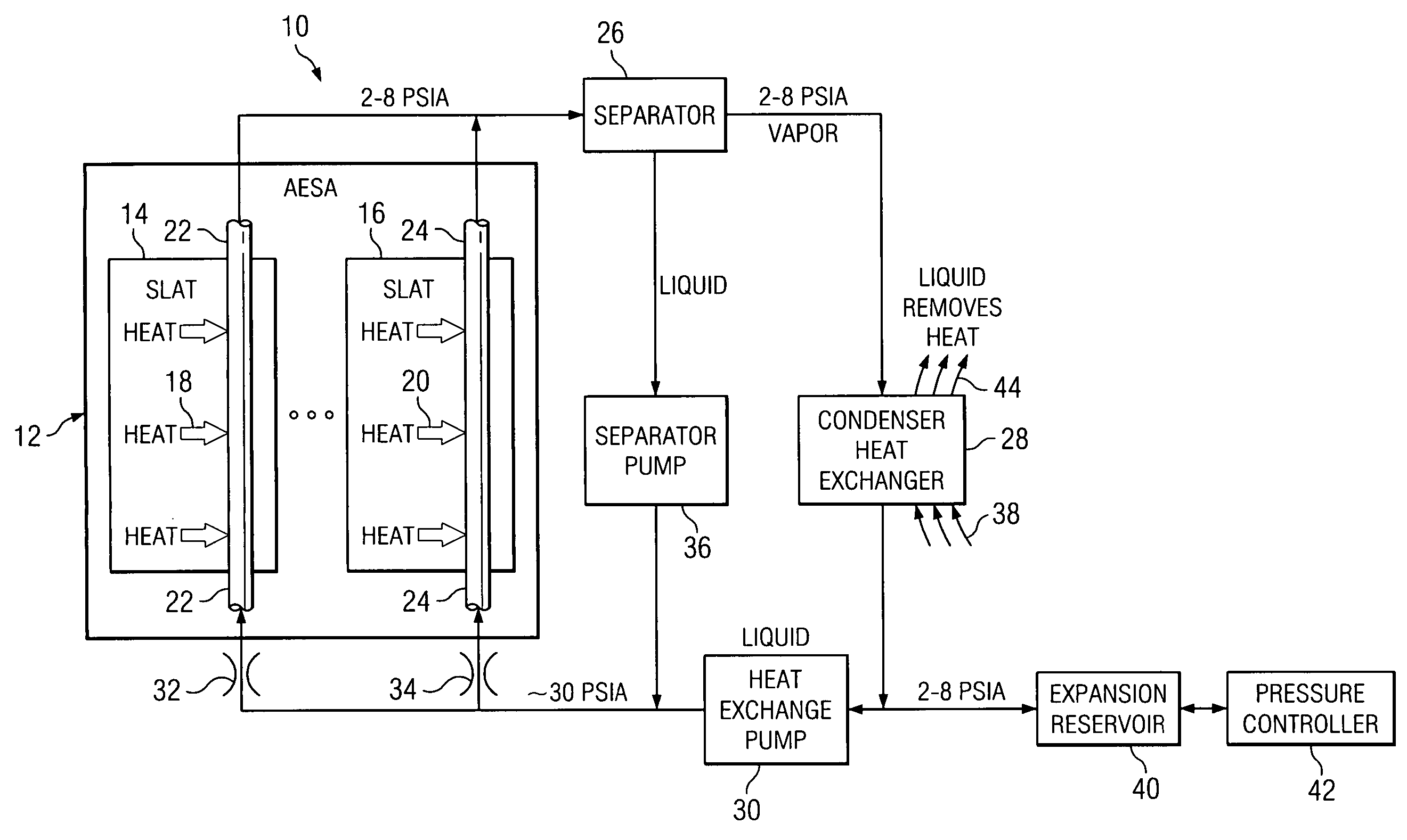
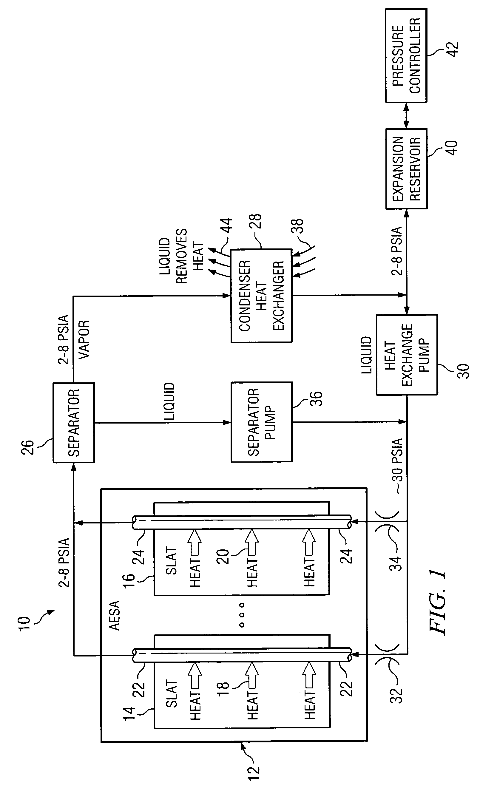
[0013]FIG. 1 is a block diagram of an apparatus 10 that includes a phased array antenna system 12. In one embodiment, the antenna system 12 includes a plurality of identical modular parts that are commonly known as slats, two of which are depicted at 14 and 16. A feature of the present invention involves techniques for controlling cooling the antenna system 12, or other heat-generating structure, so as to remove appropriate amounts of heat generated therein.

[0014]In the illustrated embodiment, the electronic circuitry within the antenna system 12 has a known configuration, and is therefore not illustrated and described here in detail. Instead, the circuitry is described only briefly here, to an extent that facilitates an understanding of the present invention. In partic...


PUM


Abstract

According to one embodiment, an apparatus includes a fluid coolant and structure which reduces a pressure of the fluid coolant through a subambient pressure at which the coolant has a cooling temperature less than a temperature of the heat-generating structure. The apparatus also includes structure that directs a flow of the fluid coolant in the form of a liquid at a subambient pressure in a manner causing the liquid coolant to be brought into thermal communication with the heat-generating structure. The heat from the heat-generating structure causes the liquid coolant to boil and vaporize so that the coolant absorbs heat from the heat-generating structure as the coolant changes state. The structure is configured to circulate the fluid coolant through a flow loop while maintaining the pressure of the fluid coolant within a range having an upper bound less than ambient pressure. The apparatus also includes a first heat exchanger for exchanging heat between the fluid coolant flowing through the loop and a second coolant in an intermediary loop so as to condense the fluid coolant flowing through the loop to a liquid. The apparatus also includes a second heat exchanger for exchanging heat between the second coolant in the intermediary cooling loop and a body of water on which the ship is disposed.

Description

TECHNICAL FIELD OF THE INVENTION[0001]This invention relates in general to cooling techniques and, more particularly, to a method and apparatus for cooling a system that generates a substantial amount of heat through use of coolant at a subambient pressure.BACKGROUND OF THE INVENTION[0002]Some types of electronic circuits use relatively little power, and produce little heat. Circuits of this type can usually be cooled satisfactorily through a passive approach, such as convection cooling. In contrast, there are other circuits that consume large amounts of power, and produce large amounts of heat. One example is the circuitry used in a phased array antenna system.[0003]More specifically, a modern phased array antenna system can easily produce 25 to 30 kilowatts of heat, or even more. One known approach for cooling this circuitry is to incorporate a refrigeration unit into the antenna system. However, suitable refrigeration units are large, heavy, and consume many kilowatts of power in...

Claims


Application Information

Patent Timeline
Patent Type & Authority Patents(United States)
IPC IPC(8): F25D23/12
CPCB63J2/02F25B23/006H01Q1/02H01Q1/34F25B2339/047
Inventor WEBER, RICHARD MARTINWYATT, WILLIAM GERALD
Owner RAYTHEON CO
Why Eureka
Try Eureka