Clutch system and method for controlling a clutch system

a technology of clutch system and clutch system, which is applied in the direction of clutches, non-mechanical actuated clutches, slip couplings, etc., can solve the problems of complex integration of sensors and clutches, and achieve the effects of less complication, reliable clutch confirmation, and quick destruction

Active Publication Date: 2010-04-29
ROBERT BOSCH GMBH
View PDF3 Cites 5 Cited by
  • Summary
  • Abstract
  • Description
  • Claims
  • Application Information

AI Technical Summary

Benefits of technology

[0004]It has been that in the clutch systems known from the prior art, problems, such as leakage, air inclusions, changes in elasticity, or temperature fluctuations and other factors on the hydraulic connection between the distance detection in the actuator and the hydraulic actuation unit of the clutch can cause the position of the adjustable clutch part, which is detected indirectly by means of the distance detection of the actuator final control element, does not match the actual position of the clutch part. The possible consequence is that at the adjustable clutch part of the hydraulic actuation unit of the clutch, the distance required for opening or closing the clutch is not set, and as a result, a clutch may for instance scrape more often than necessary and can be quickly destroyed. Furthermore, the clutch can be damaged by overly long disengagement distances.
[0005]In the clutch system of the invention having the characteristics of independent claim 1, and in the method of the invention for controlling a clutch system having the characteristics of independent claim 8, it is possible to overcome these disadvantages. For that purpose, it is provided that the actuation unit of the clutch has a mechanical stop that limits the adjustment of the clutch part. Furthermore, means are provided which monitor the pressure in the hydraulic system, or a trigger signal of the actuator, such as the current through an electric motor of the electrohydraulic actuator, and detect contact of the clutch part with the stop on the basis of a characteristic change, which occurs then, in the pressure in the hydraulic system or in the trigger signal. Detecting the contact of the clutch part with the stop is effected for instance by means of a pressure sensor, which is preferably located on the actuator, or by evaluating the current at an electric motor of the electrohydraulic actuator. The sensors and / or evaluation means required for this purpose can advantageously be disposed remotely from the clutch, at a location where they involve less complication. Expensive sensors at the actuation unit can thus be dispensed with. This is highly advantageous, since at the actuation unit of the clutch, ambient conditions that are critical for sensors are present and valuable space is thus lost because of the sensors. By detecting the contact of the clutch part with a defined stop, a plausibility test of the clutch state is done in the control unit of the actuator, thus excluding sources of error in the hydraulic connection. The information thus obtained is advantageously used in the control unit for adapting the control for the future triggering of the actuator or for generating diagnosis signal.
[0006]Advantageous embodiments and further developments of the invention are made possible by the provisions recited in the dependent claims.
[0007]It is advantageous if the electrohydraulic actuator has an actuator final control element that is adjustable by a predeterminable regulating distance, and means are provided which detect the regulating distance of the actuator final control element and forward it to the control unit. The pressure in the hydraulic system detected via pressure sensors, or the detected current value through an electric motor of the actuator, rises sharply upon an approach to the stop. The regulating distance of the actuator final control element at which this rise takes place reflects the position of the stop under all system factors, such as elasticities in the hydraulic connection and connection pieces and seals, and can be used upon the next clutch actuation for predetermining the distance at the actuator and thus for reliable clutch confirmation.
[0008]The control unit may have a memory, in which a relationship between the clutch actuation and the regulating distance of the actuator final control element is stored that is used for triggering the actuator. This relationship may for instance be a characteristic curve stored in the memory. The contact of the clutch part with the stop that is detected in the control unit is then especially advantageously used for adapting the relationship between the clutch actuation and the regulating distance of the actuator final control element in the control unit. The relationship between the clutch actuation and the regulating distance of the actuator final control element may for instance be a relationship between the pressure in the hydraulic system, or a variable affected by it, and the regulating distance of the actuator final control element.
[0009]It is also advantageous that means are provided which, if contact of the clutch part with the stop is detected, compare the value then present for the regulating distance of the actuator final control element, or a variable derived from it, with at least one threshold value and generate an error signal as a diagnosis signal if the at least one threshold value is exceeded. This embodiment of the invention is based on the thought that if the contact of the clutch part is detected at a regulating distance position of the actuator final control element that is outside a predetermined safe range, a major error in the clutch system (such as large quantities of trapped air) is present. Ascertaining the contact point can thus be employed for diagnostic purposes.

Problems solved by technology

The known devices in some cases have sensors for detecting the adjusting distance of an adjustable clutch part of the actuation unit, and the sensors are integrated with the clutch in a complicated way.

Method used


Image

  • Clutch system and method for controlling a clutch system
  • Clutch system and method for controlling a clutch system
  • Clutch system and method for controlling a clutch system

Examples


Embodiment Construction

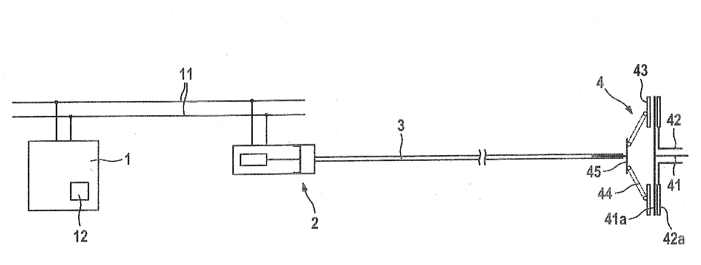
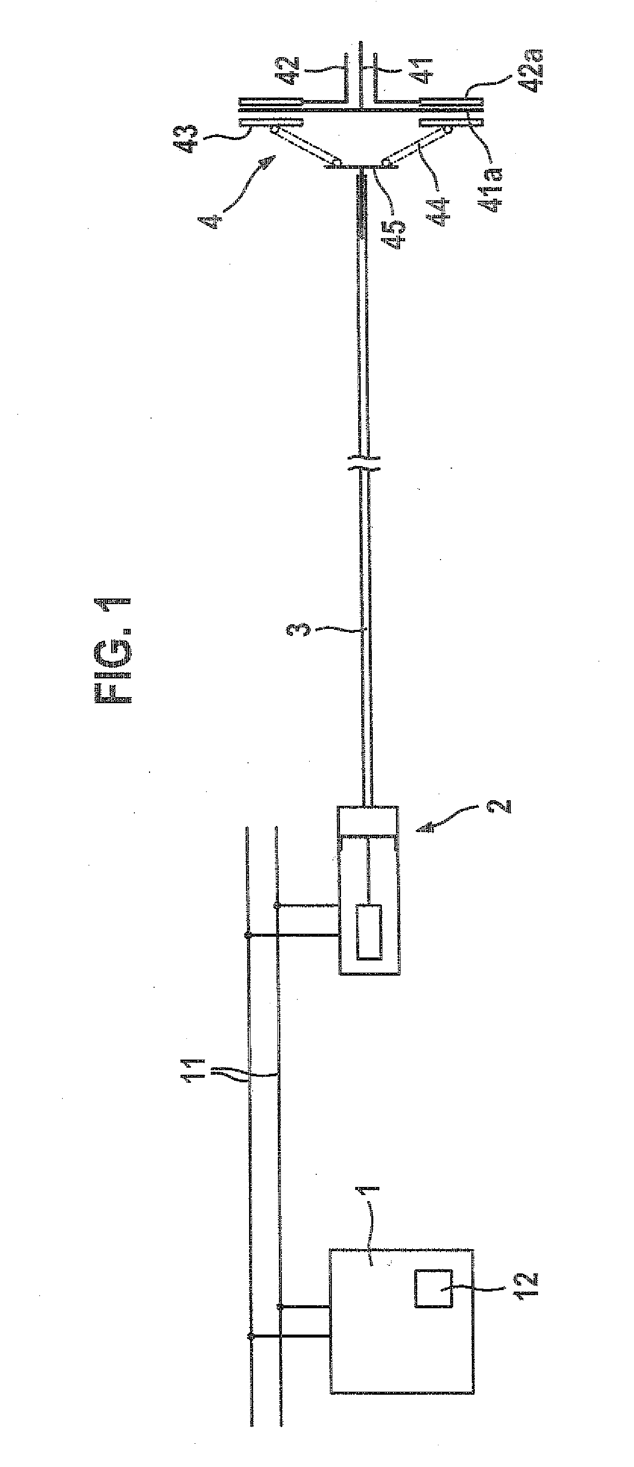
[0016]In FIG. 1, an automated clutch system is shown schematically. The clutch system includes a control unit 1, which is for instance disposed in an engine control unit and is connected electrically to an electrohydraulic actuator 2 via a data bus 11, such as a CAN bus. The hydraulic connection of the electrohydraulic actuator is connected via a hydraulic connection 3 to a clutch 4.

[0017]The clutch 4 has a clutch input side 42 and a clutch output side 41, which can be coupled with one another for connecting and disconnecting a force transmission path. To that end, the clutch has a hydraulic actuation unit, which acts upon a disengagement layer 45 which is connected to a pressure plate 43, for instance via a clutch spring 44. The pressure plate 43 is pressed by the clutch spring 44 against the clutch disk 41a and the latter is pressed against the disk flywheel 42a, as a result of which the clutch input side 42 (input shaft) is mechanically connected to the clutch output side 41 (out...


PUM


Abstract

The invention relates to a device and to a method for controlling a coupling system having a coupling provided with a hydraulic actuation system, which includes an adjustable coupling part for connecting and separating a power transmission path between a coupling input side and a coupling output side, a hydraulic connection that connects the actuation unit to an electrohydraulic actuator that is arranged outside the coupling, and a control unit for controlling the actuator. The hydraulic connection forms a hydraulic system together with hydraulic components of the actuation unit and the actuator. According to the invention, a mechanical stop that delimits the adjustment of the coupling part on the actuation unit is formed. A pressure sensor monitors the pressure in the hydraulic system or a control signal of the actuator. The pressure sensor detects an installation of the coupling part on the stop based on occurring characteristic alterations of the pressure in the hydraulic connection or the control signal and controls the electrohydraulic actuator in accordance therewith and/or produces a diagnosis signal.

Description

PRIOR ART[0001]The invention is based on a clutch system as generically defined by the preamble to independent claim 1 and on a method for controlling a clutch system as generically defined by the preamble to independent claim 8.[0002]One such clutch system is known for instance from Bosch Kraftfahrtechnisches Taschenbuch [Automotive Handbook], Vieweg (Braunschweig and Wiesbaden), 1999, pages 590f. The automated clutch system shown there for instance has a clutch with a hydraulic actuation unit for connecting and disconnecting a force transmission path between a clutch input side and a clutch output side; a hydraulic connection between the actuation unit and an electrohydraulic actuator; and a control unit for triggering the actuator. In these systems, the distance at the actuation unit of the clutch or at the disengaging gear must be known, to enable controlling the frictional moment at the clutch as precisely as possible. For triggering the hydraulic actuation unit of the clutch i...

Claims


Application Information

Patent Timeline
Patent Type & Authority Applications(United States)
IPC IPC(8): F16D48/06
CPCF16D29/005F16D48/066F16D2500/1024F16D2500/3024F16D2500/70235F16D2500/5108F16D2500/511F16D2500/70217F16D2500/3026
Inventor SCHULER, RALFWEBER, WERNERSCHMOLL GENANNT EISENWERTH, KASPARBAWIDAMANN, ALEXANDER
Owner ROBERT BOSCH GMBH
Why Eureka
Try Eureka