
Reciprocating Lift and Thrust Systems

a technology of thrust system and reciprocating lift, which is applied in the direction of vertical landing/take-off aircraft, ornithopters, transportation and packaging, etc., can solve the problems of poor safety record, poor safety, and insufficiently high lift, and achieves improved safety and reliability, and the cost of the driver system may be potentially much lower.

Pending Publication Date: 2020-11-19
CAO YIDING
View PDF14 Cites 4 Cited by
  • Summary
  • Abstract
  • Description
  • Claims
  • Application Information

AI Technical Summary

Benefits of technology

This patent describes a new system for creating aircraft that can takeoff, land, and fly without using a runway. The system uses a reciprocating airfoil that has a high lift-to-drag ratio, which means it can generate more lift with less weight than traditional rotorcraft. The airfoil moves in a reciprocating motion, which helps to cancel out the inertia forces and moments associated with its motion. The system can be used in a variety of vehicles, including vertical takeoff and landing vehicles, flying cars, and more. It is also more cost-effective and has greater performance and safety advantages compared to traditional rotorcraft. The system can be easily balanced and has modularity and controllability, making it ideal for different types of vehicles. Overall, this new system offers a new way to create efficient and reliable aircraft that can perform a variety of tasks.

Problems solved by technology

However, the generation of a sufficiently high lift requires a substantially high aircraft speed, and subsequently, a runway for aircraft takeoff or landing is needed.
But the use of the helicopter so far is rather limited, far from being a mass transportation means, which may represent a grand challenge.
The challenges that hold back the use of helicopters may include, but not limited to, the following: (1) Significant vibratory loads in forward flight, very complex aerodynamic environments involving the wide and intense vorticity field released by the main rotor, and blade-vortex interactions, which may cause adverse operational conditions for helicopters including tiltrotor helicopters, such as the vortex ring state; (2) Poor safety track record based on their fatal accident rates in comparison with fixed-wing airplanes and difficult to operate by non-professional pilots; (3) Much lower global lift-to-drag ratio of the main rotor during takeoff and landing as well as cruise than that of fixed-wing aircraft, resulting in substantially increased power consumption and reduced flight range; (4) Generation of very strong wind and loud noise during takeoff or landing, both of which are negative factors that may hinder mass adoption of the helicopter; and (5) System complexity, anti-torque mechanisms, high costs, and large footprint.
However, they may also add additional complexity and costs, which may further hinder the mass adoption of the helicopter.

Method used


Image

  • Reciprocating Lift and Thrust Systems
  • Reciprocating Lift and Thrust Systems
  • Reciprocating Lift and Thrust Systems

Examples


embodiment 108

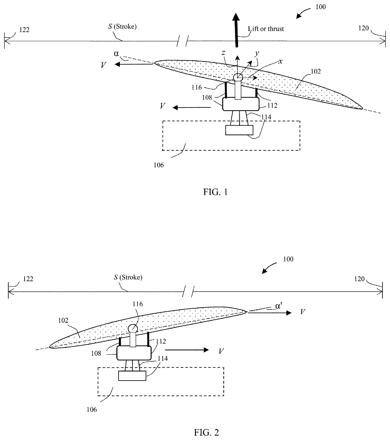
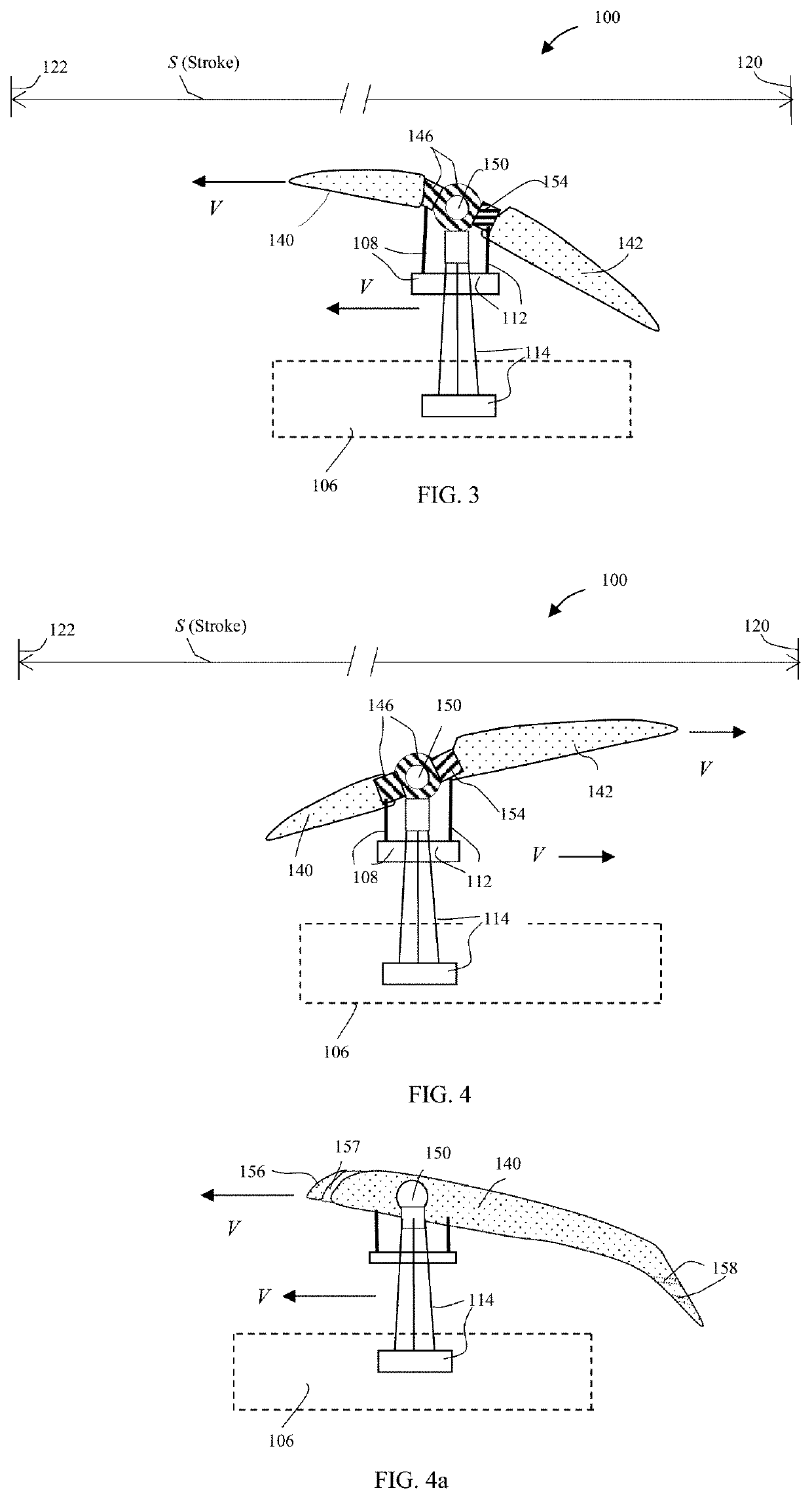
[0053]FIG. 1 shows a schematic illustration of a sectional view of a reciprocating lift or thrust system according to an embodiment of the subject invention. Referring to FIG. 1, the system 100 comprises an airfoil 102 and a reciprocating driver 106 that may produce a reciprocating motion of the airfoil 102 with a stroke S. Said stroke may be defined based on any section of the airfoil and it may be related to a reference section such as a midsection of the airfoil. In FIG. 1, said airfoil 102 travels toward the left dead-end 122 of the stroke with a positive angle of attack α, producing a lift or thrust. The system further comprises a control unit with an embodiment 108 or 112 shown in the figure. Near or at the left dead-end 122, the activation of the control unit 108 or 112 may generate a counter-clockwise rotation of the airfoil around a joint mechanism 116 by an angle as the airfoil changes direction and moves from the left end 122 toward the right end 120 with an angle of atta...

embodiment 200

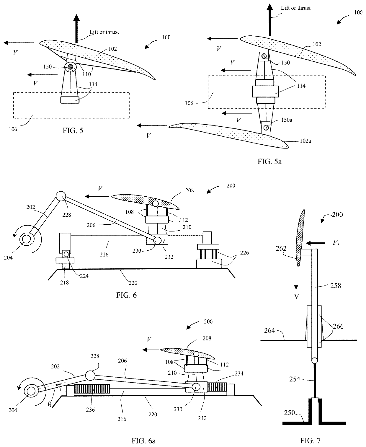
[0064]Said reciprocating mechanical driver maybe, but not limited to, a slider-crank mechanism driver, a cam-follower mechanism driver, a scotch yoke mechanism driver, a swashplate mechanism driver, or a wobble (Nutator or Z-crank) driver. FIG. 6 shows schematically an embodiment 200 of this invention with an airfoil 208 driven by a slider-crank mechanism driver. The airfoil 208 is driven by a crankshaft 204 through a crank arm 202 and a connecting rod 206. The crankshaft 204 in turn is driven by a power system (not shown). Through the connecting rod 206 as well as a supporting structure 210 that may include a roller or bearing structure 212, the rotation of the crankshaft 204 creates a reciprocating motion of the airfoil 208. Said roller or bearing 212 may be mounted on a track or guide structure 216, and slide, together with the airfoil 208, along the track 216. The track 216 may work as a guide for the reciprocating motion of the airfoil assembly 208 and carry loads of the lift o...

embodiment 300

[0068]Another embodiment of the reciprocating driver is an electromagnetic driver. FIG. 8 shows schematically an embodiment 300 of the electromagnetic driver, employing a pair of electromagnets 302 and 304 and a pair of permanent magnets 310 and 312. Said electromagnets may be energized by a power source such as a battery system (not shown) of suitable current and voltage. In the case of FIG. 8, the polarity of the electromagnet is set in such a way that it repels the corresponding permanent magnet when the electromagnet is energized. Through connecting rods 314 and 316, said permanent magnets 310 and 312 are connected to an airfoil assembly 350 through supporting structures 320. Said supporting structure 320 includes a bearing or rolling slider 324 that may slide along a track 328. When the permanent magnet 312 is near the right dead end of a reciprocating stroke, the electromagnet 302 is energized, and the generated repulsive electromagnetic force pushes the permanent magnet 312 a...


PUM


Abstract

A reciprocating lift and thrust system include at least an airfoil and a reciprocating driver configured to produce a reciprocating motion of the airfoil. The system may further include a control unit to change or maintain a suitable angle of attack of the airfoil for lift or thrust as well as to facilitate the cyclic control of the flying vehicle driven by the reciprocating system. The lift and thrust system may be deployed in a module that includes at least two reciprocating airfoils (RAs) and is configured to substantially cancel out the inertia forces and moments associated with the individual airfoils. The reciprocating driver maybe, but not limited to, a mechanical, electromagnetic, electrical, or hydraulic driver. The embodiments of the subject invention provide novel and advantageous RA-driven aircraft, RA-driven flying motor vehicles, and RA-driven watercraft.

Description

[0001]This application is a national stage application of the International Patent Application: Reciprocating Lift and Thrust Systems (PCT / US2019 / 021636).BACKGROUND OF THE INVENTION[0002]The use of airfoils by fixed-wing aircraft has the benefit of attaining an increased lift as compared to the thrust needed to overcome the aerodynamic resistance and sustain the flight of the aircraft. In general, a fixed-wing aircraft with finite-span airfoils may have a lift ten times greater than the needed thrust that may be provided by a jet engine or propeller, resulting in a great leverage ratio by using fixed wings. In conjunction with other advantages, the fixed-wing aircraft have become a mass-transportation means in most countries. However, the generation of a sufficiently high lift requires a substantially high aircraft speed, and subsequently, a runway for aircraft takeoff or landing is needed.[0003]Helicopters or rotorcraft have been developed for vertical takeoff and landing as well a...

Claims


Application Information

Patent Timeline
Patent Type & Authority Applications(United States)
IPC IPC(8): B64C33/02B64C29/00
CPCB64C29/0008B64C33/02B64C37/00B64C3/385Y02T50/10B64U10/25B64U30/29
Inventor CAO, YIDING
Owner CAO YIDING
Learn More