Apparatus for testing a device with a high frequency signal

a high-frequency signal and apparatus technology, applied in the direction of testing circuits, semiconductor/solid-state device testing/measurement, instruments, etc., can solve the problems of occupying valuable space in the apparatus, long coaxial cables may sag,

Inactive Publication Date: 2009-12-01
ADVANTEST CORP
View PDF20 Cites 4 Cited by
  • Summary
  • Abstract
  • Description
  • Claims
  • Application Information

AI Technical Summary

Benefits of technology

[0006]The present invention provides an apparatus for testing a device with a high frequency signal that overcomes the above limitations of conventional ATE systems. The apparatus of the present invention delivers a high frequency signal directly to a loadboard with a coaxial cable. The coaxial cable allows the signal to be delivered to a location at or near the device on the loadboard. This reduces the length of the trace to the device. Furthermore, there is almost no electrical loss associated with a coaxial cable. The coaxial cable also has shielding which works to avoid milli-volt fluctuations by acting as a stable ground.
[0009]The first end of the coaxial cable communicates with the testing module. In one embodiment, the first end communicates with the testing module by being directly connected to a given module. In another embodiment, the first end communicates with the testing module through a second coaxial cable. The second coaxial cable is used between the first end of the first coaxial cable and the testing module to allow communication therebetween. Using two coaxial cables avoids the need for a single lengthy coaxial cable in a large testing apparatus. A lengthy coaxial cable may sag, may become entangled with other wiring in the apparatus and may take up valuable space in the apparatus. The second coaxial cable can also be a semi-rigid coaxial cable. It can connect to the first coaxial cable through a threaded connection or push-on connection, such as a blind-mate connection. The second coaxial cable can also be directly connected to the testing module through a threaded connection or a push-on connection.
[0012]A plurality of coaxial cables transmit test signals at or near the device from the testing modules. The coaxial cables can communicate exclusively with the second testing module that transmits the high frequency signal. The coaxial cables can also communicate with the first testing module to deliver the low frequency signal to the circuit board. Coaxial cables can be used for such a low frequency signal given their many benefits such as acting as a stable ground.

Problems solved by technology

A lengthy coaxial cable may sag, may become entangled with other wiring in the apparatus and may take up valuable space in the apparatus.

Method used


Image

  • Apparatus for testing a device with a high frequency signal
  • Apparatus for testing a device with a high frequency signal
  • Apparatus for testing a device with a high frequency signal

Examples


Embodiment Construction

[0018]In the following description of embodiments, reference is made to accompanying drawings which form a part hereof and in which is shown by way of illustration specific embodiments in which the invention may be practiced. It is to be understood that other embodiments may be utilized and structural changes may be made without departing from the scope of the preferred embodiments of the present invention.

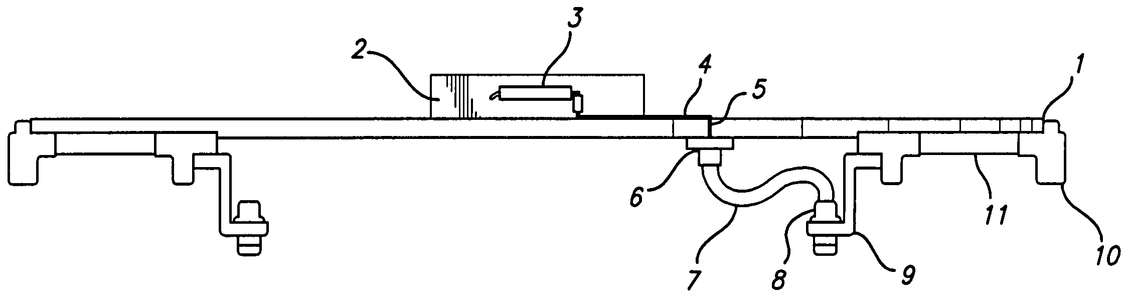
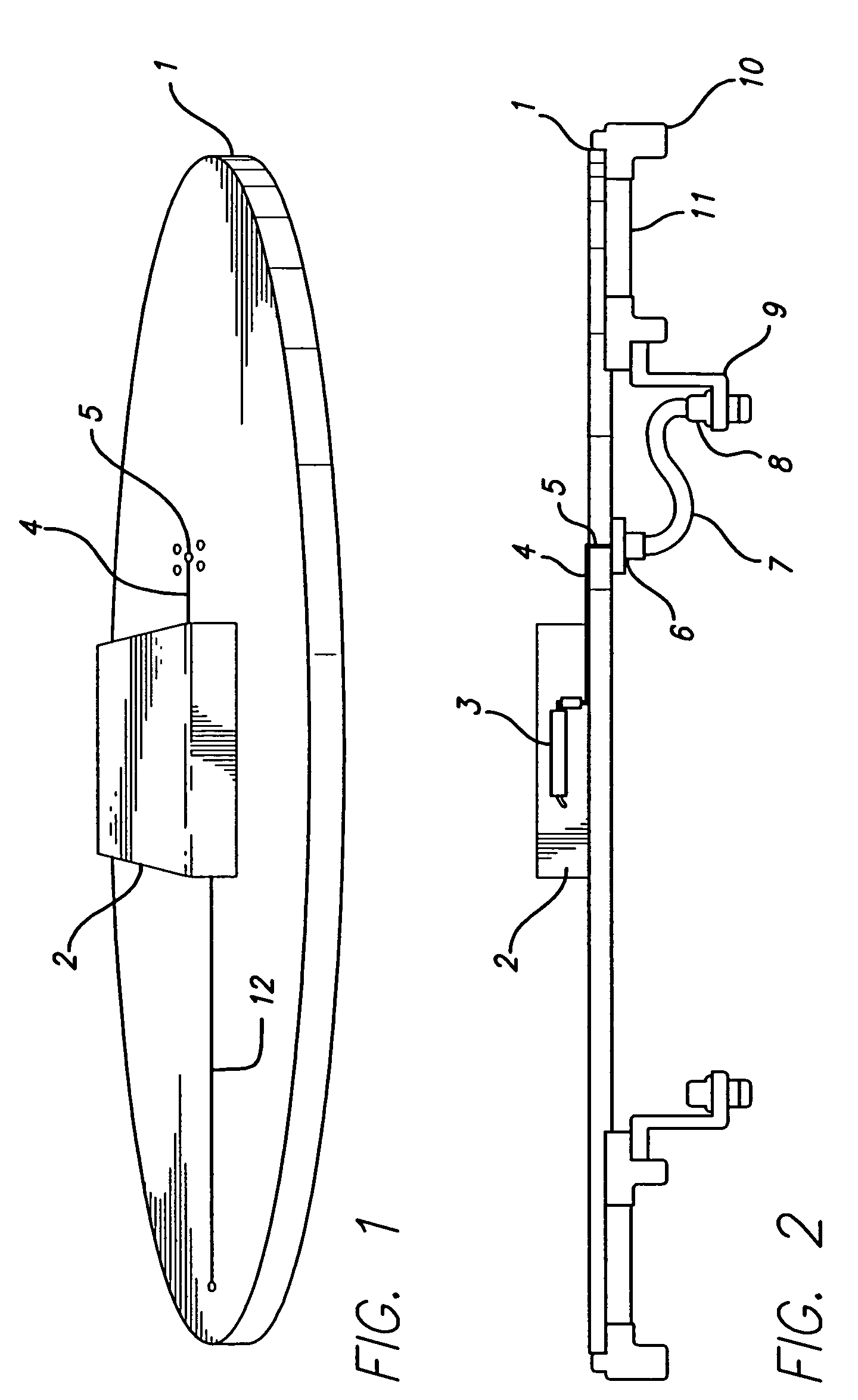
[0019]FIG. 1 shows a schematic illustration of a circuit board embodying the present invention while FIG. 2 shows a schematic partial side illustration of a circuit board embodying the present invention with additional detail relating to a coaxial cable connection and support. The following discussion references both FIG. 1 and FIG. 2 and like reference numerals refer to the same element.

[0020]Circuit board 1 is a printed circuit board having an circular shape. Circuit board 1 can be any other shape, such as elliptical, rectangular or square. On circuit board 1, a socket 2 is moun...


PUM


Abstract

The present invention provides an apparatus for testing a device with a high frequency signal, such as an RF signal. The apparatus delivers a high frequency signal directly to a loadboard with a coaxial cable. The coaxial cable can deliver the signal to a location at or near the device on the loadboard. The cable can connect to the loadboard through a threaded connection. The other end of the cable can connect to a testing module or another cable. The apparatus can further comprise a section or housing between the circuit board and the testing module to provide support for the cables and their respective connections. The apparatus can further provide connections for both high frequency testing and low frequency testing.

Description

CROSS-REFERENCE TO RELATED APPLICATIONS[0001]This application claims priority to U.S. provisional application Ser. No. 60 / 525,786 entitled “Test Head Modules for RF and Mixed-Signal / Analog Testing,” filed Nov. 26, 2003, and is related to U.S. non-provisional application Ser. No. 10 / 779,031 entitled “Synchronization of Modules for Analog and Mixed Signal Testing in an Open Architecture Test System,” filed Feb. 13, 2004, with the contents of each incorporated herein by reference for all purposes.BACKGROUND OF THE INVENTION[0002]The present invention relates to an apparatus for testing a device with a high frequency signal and, more particularly, to an apparatus for testing a device by delivering a high frequency signal with a coaxial cable at or near the device.[0003]Automatic test equipment systems or ATE systems are used to test devices such as semiconductor devices. An ATE system typically comprises a tester that generates test signals which are transmitted to a test head. The test...

Claims


Application Information

Patent Timeline
Patent Type & Authority Patents(United States)
IPC IPC(8): G01R31/00G01R31/28H01R9/05
CPCG01R31/2889G01R31/26H01L22/00
Inventor ITO, YOSHIMASA
Owner ADVANTEST CORP
Why Eureka
Try Eureka