Method and device for improving the starting response of an internal combustion engine

a technology of internal combustion engine and starting response, which is applied in the direction of combustion-air/fuel-air treatment, electric control, ignition automatic control, etc., can solve the problems of short time period between injection and ignition, and high emissions, so as to improve the evaporation of fuel, reduce the effect of compression and great temperature increas

Inactive Publication Date: 2007-08-14
ROBERT BOSCH GMBH
View PDF10 Cites 13 Cited by
  • Summary
  • Abstract
  • Description
  • Claims
  • Application Information

AI Technical Summary

Benefits of technology

[0011]The object of the present invention is fully obtained via these features. By producing a high percentage of fuel vapor in the combustion chamber charge that will not be ignited until subsequent starting, a more homogeneous distribution of the fuel in the combustion chamber charge with air is obtained. The ignitability of the combustion chamber charge is improved as a result. In addition, the percentage of fuel in the combustion chamber involved in combustion increases. As a result of the more complete combustion of the combustion chamber charge, more torque is developed and pollutant emissions are reduced.

Problems solved by technology

The short time period between injection and ignition is usually not long enough to obtain a homogeneous fuel / air mixture.
In addition, only small fuel droplets can evaporate completely in the short period of time between injection and ignition.
This results in higher emissions and higher specific fuel consumption.
In addition, the percentage of potential thermodynamic energy in the combustion chamber charge that is converted to mechanical work at start-up can be so small due to insufficient mixture formation that the starting response of the internal combustion engine is negatively affected.
This is a disadvantage, in particular, when the impairment of the starting response should not or can not be compensated for by an independently-driven starter (e.g., an electric starter).

Method used


Image

  • Method and device for improving the starting response of an internal combustion engine
  • Method and device for improving the starting response of an internal combustion engine
  • Method and device for improving the starting response of an internal combustion engine

Examples


Embodiment Construction

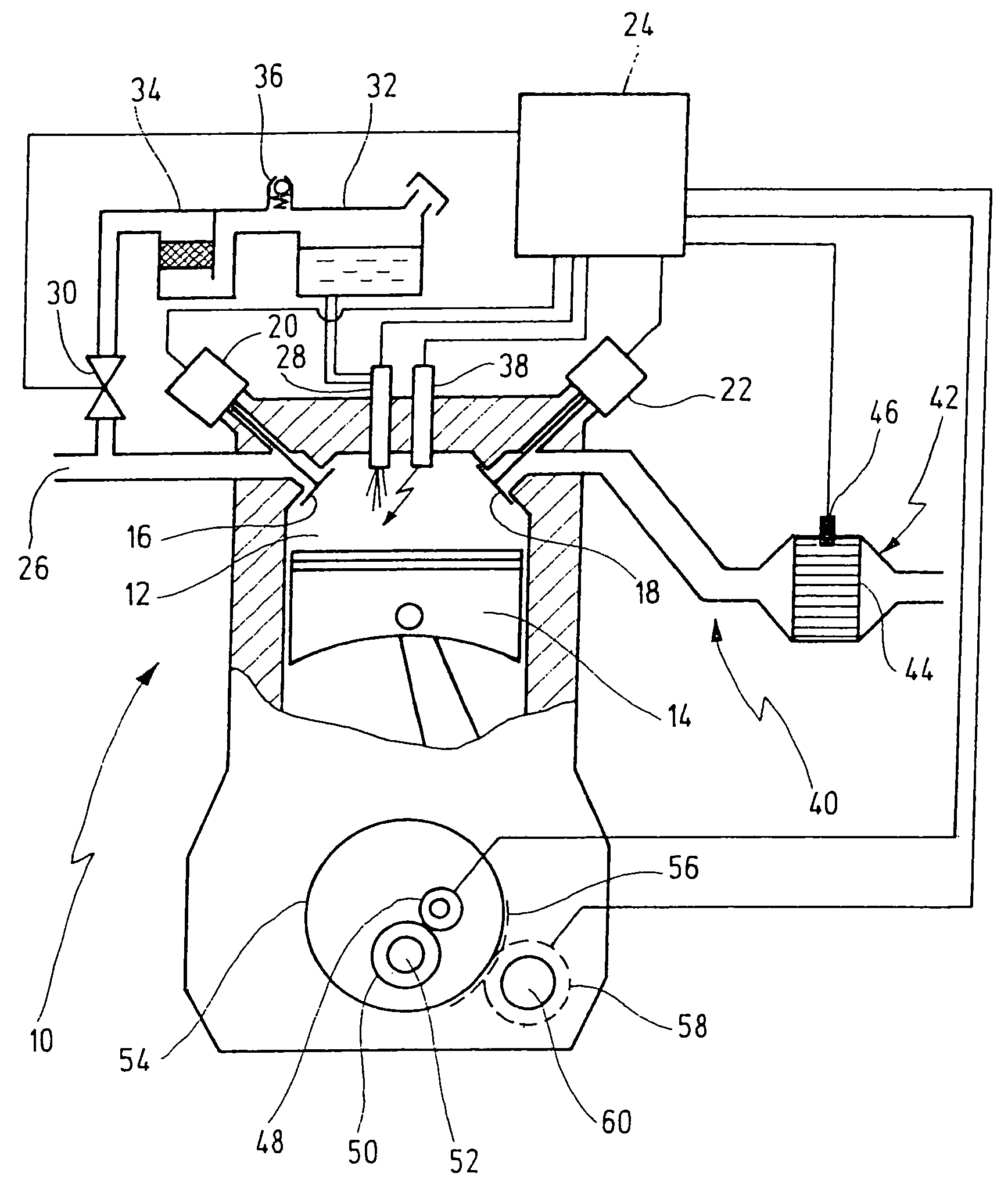
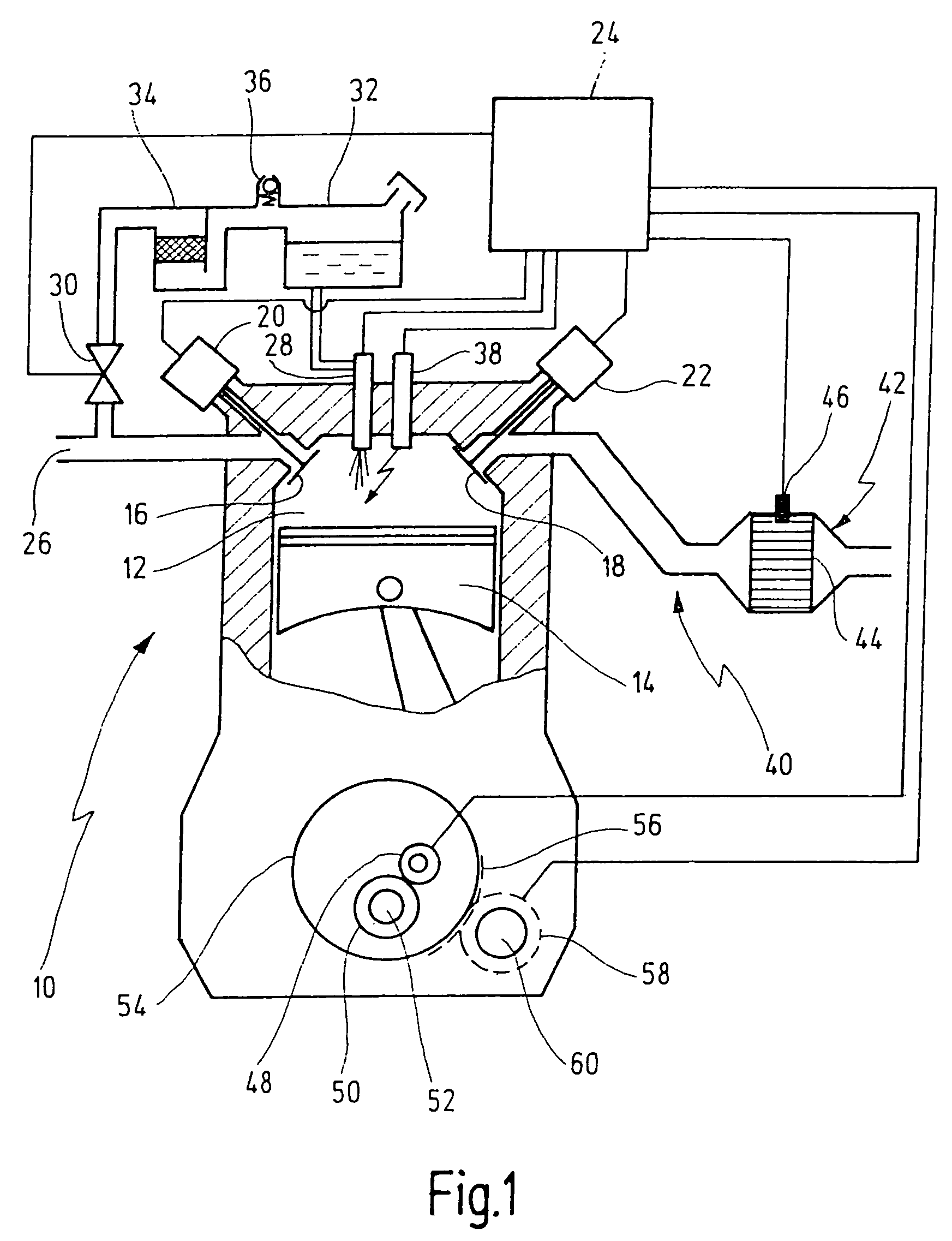
[0043]FIG. 1 shows a schematic depiction of the overall view of an internal combustion engine 10, in a partial cross section.

[0044]Internal combustion engine 10 includes at least one combustion chamber 12 that is sealed shut in a movable manner by a piston 14. The charging of combustion chamber 12 with fuel / air mixture and with burned residual exhaust gas resulting from combustion of the fuel / air mixture is controlled by at least one intake valve 16 and at least one exhaust valve 18. To this end, intake valve 16 is coupled with an intake-valve control element 20, and exhaust valve 18 is coupled with an exhaust-valve control element 22. Intake-valve control element 20 and exhaust-valve control element 22 can be realized as cams, the phase positions of which—relative to each other and / or to the crankshaft of internal combustion engine 10—are fixedly predetermined or are variable. As an alternative, intake-valve control element 20 and exhaust-valve control element 22 can be realized as...


PUM


Abstract

The present invention relates to methods for charging at least one combustion chamber (12) of a spark-ignition combustion engine (10) with fuel and air. At least one combustion chamber charge is produced during a shutoff phase of the internal-combustion engine (10) and is ignited when the internal-combustion engine (10) is subsequently started. The methods are characterized in that, during the shutoff phase, at least one measure is taken to produce a high percentage of fuel vapor in the combustion chamber charge. The present invention also relates to a control unit for controlling the methods.

Description

CROSS-REFERENCE[0001]The invention described and claimed hereinbelow is also described in PCT / DE2004 / 000411, filed on Mar. 4, 2004 and DE 103 22 361.4, filed on May 9, 2003. This German Patent Application, whose subject matter is incorporated here by reference, provides the basis for a claim of priority of invention under 35 U.S.C. 119 (a)-(d).BACKGROUND OF THE INVENTION[0002]The present invention relates to methods for charging at least one combustion chamber of a spark-ignition combustion engine with fuel and air, at least one combustion chamber charge being produced during a shutoff phase of the internal-combustion engine and being ignited when the internal-combustion engine is subsequently started. The present invention also relates to an electronic control unit that controls a method of this type.[0003]Conventional internal combustion engines are started with the aid of an independently-driven starter. The independently-driven starter, usually an electric starter, turns the int...

Claims


Application Information

Patent Timeline
Patent Type & Authority Patents(United States)
IPC IPC(8): F02M1/00F02D41/06F02N17/00F01N3/20F02D41/04F02N11/08F02N99/00F02P5/04
CPCF02D41/0032F02D41/025F02N11/0814F02N99/006F02P5/045F01N3/2006F02D41/042Y02T10/26Y02T10/48F02D41/062Y02A50/20Y02T10/12Y02T10/40
Inventor SIEBER, UDOLAUBENDER, JOCHENCASAL KULZER, ANDRE-FRANCISCO
Owner ROBERT BOSCH GMBH
Why Eureka
Try Eureka