Connector

a technology of connecting rods and connectors, applied in the direction of coupling contact members, coupling device connections, coupling/insulating coupling contact members, etc., can solve the problems of complex structure, increased contact size, and increased manufacturing process, so as to achieve high retaining force, increase retaining force, and high retaining force

Inactive Publication Date: 2007-08-14
JST MFG CO LTD
View PDF15 Cites 6 Cited by
  • Summary
  • Abstract
  • Description
  • Claims
  • Application Information

AI Technical Summary

Benefits of technology

[0008]In view of such a problem described above, it is an object of the present invention to provide a connector which is provided with a compact engagement structure providing a high retaining force. More specifically it is an object of the present invention to provide a connector in which deterioration of the retaining force caused by chipping off of an engaging wall by an engaging piece is prevented even when a contact body is formed of hard metal for enabling usage under severe conditions such as high temperature.
[0012]With the provision of the shoulder of inverted tapered shape, even when the electric cable which is crimped to the contact body is pulled toward the rear end of the housing, the engaging piece of the contact body lifts smoothly from the distal end to the proximal end along the inclination of the shoulder, and is hardly comes off. The engaging piece lifted from the distal end to the proximal end of the shoulder is engaged at the position in the vicinity of the proximal end of the shoulder. When the engaging piece is engaged with the proximal portion, a force to pull the contact body is received by a wide portion of the shoulder, the engagement retaining force can be increased.
[0015]On the other hand, according to the invention described in (2), since the engaging area can be increased by chamfering the inner edge at the distal end of the engaging piece, the retaining force can be increased without bending the engaging piece or increasing the lifting height of the engaging piece. Also, since the shoulder can be prevented form being chipped off by the engaging piece, lowering of the retaining force can be prevented.
[0019]According to the invention described in (4), the contact body is formed of a metal plate of titan-copper containing titan and copper. The titan-copper is superior in resiliency and hard material, and hence permanent strain of the engaging piece is prevented and the retaining force can be improved. In particular, the contact body including the engaging piece is formed of titan-copper plate, it is preferable to chamfer the inner edge of the distal end of the engaging piece in order to prevent the shoulder from chipping off. Since the titan-copper has a high stress-alleviating property even under the severe environment which increases in temperature, the connector including the titan-copper contact body can be used under the high-temperature environment such as a power source for a lamp.
[0022]According to the invention described in (5), by forming a projected portion at the midsection of the engaging piece so as to project in the direction in which the engaging piece is punched out and lifted up, a force generated by pulling the electric cable is dispersed on the inner wall portion which defines the housing storage chamber to enhance the retaining force between the contact and the housing.
[0029]According to the invention, the engaging piece can be engaged smoothly with the inner wall of the housing without upsizing the engaging piece provided on the contact. Therefore, the engaging piece can be downsized and its retaining force can be increased. In particular, when the shoulder for engaging the engaging piece is formed into an inverted tapered shape, and the inner side of the distal end of the engaging piece is formed into a smooth surface, a high retaining force is obtained by a gradually lifting structure of the smooth surface along the inverted taper, and the shoulder is prevented from being chipped out by the engaging piece, whereby the high retaining force can be maintained.

Problems solved by technology

However, since the engaging piece of the contact disclosed in Patent Document 1 is bent at two positions, the structure is complex and the manufacturing process becomes also complex.
Since the engaging piece is bent at the midsection, the length of the engaging piece required for lifting the engaging piece to a predetermined height increases in comparison with the case of not bending at the midsection, which may lead to upsizing of the contact.
In particular, when the contact body including the engaging piece is formed by hard metal in order to cope with the usage under severe conditions such as high temperature, the engaging wall is chipped off by the engaging piece and deterioration of the retaining force may be resulted.

Method used


Image

  • Connector
  • Connector
  • Connector

Examples


first embodiment

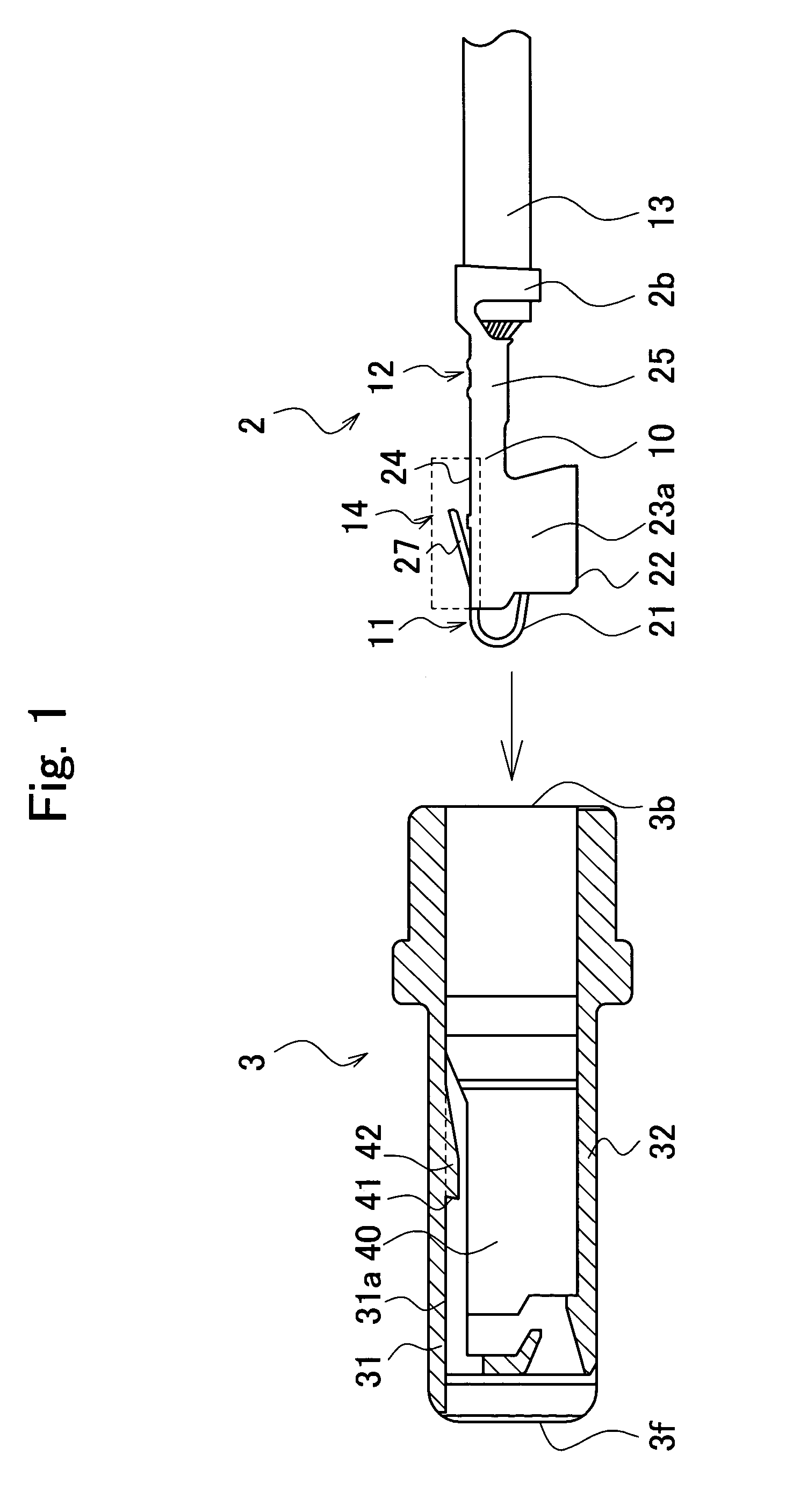
[0040]FIG. 1 is a drawing showing a female connector 1 according to the invention, which includes a contact of socket type (“socket contact”) 2 and a housing for socket contact (“socket housing”) 3 arranged so as to oppose to each other. The socket contact 2 includes an electric cable 13 and a socket contact body 10 connected to the end of the electric cable 13.

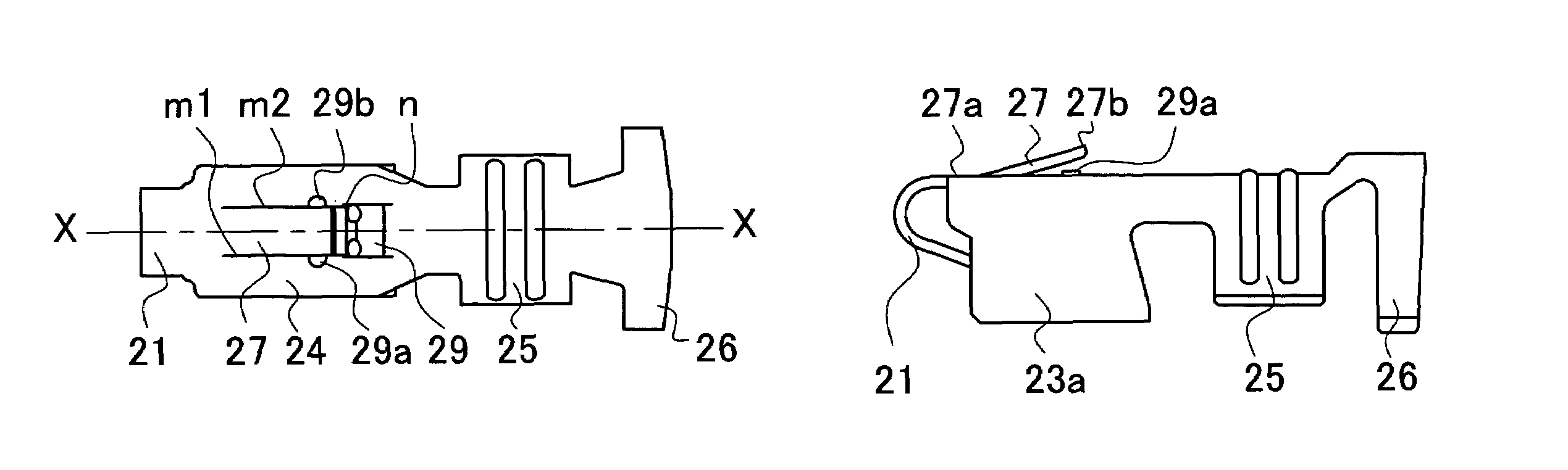
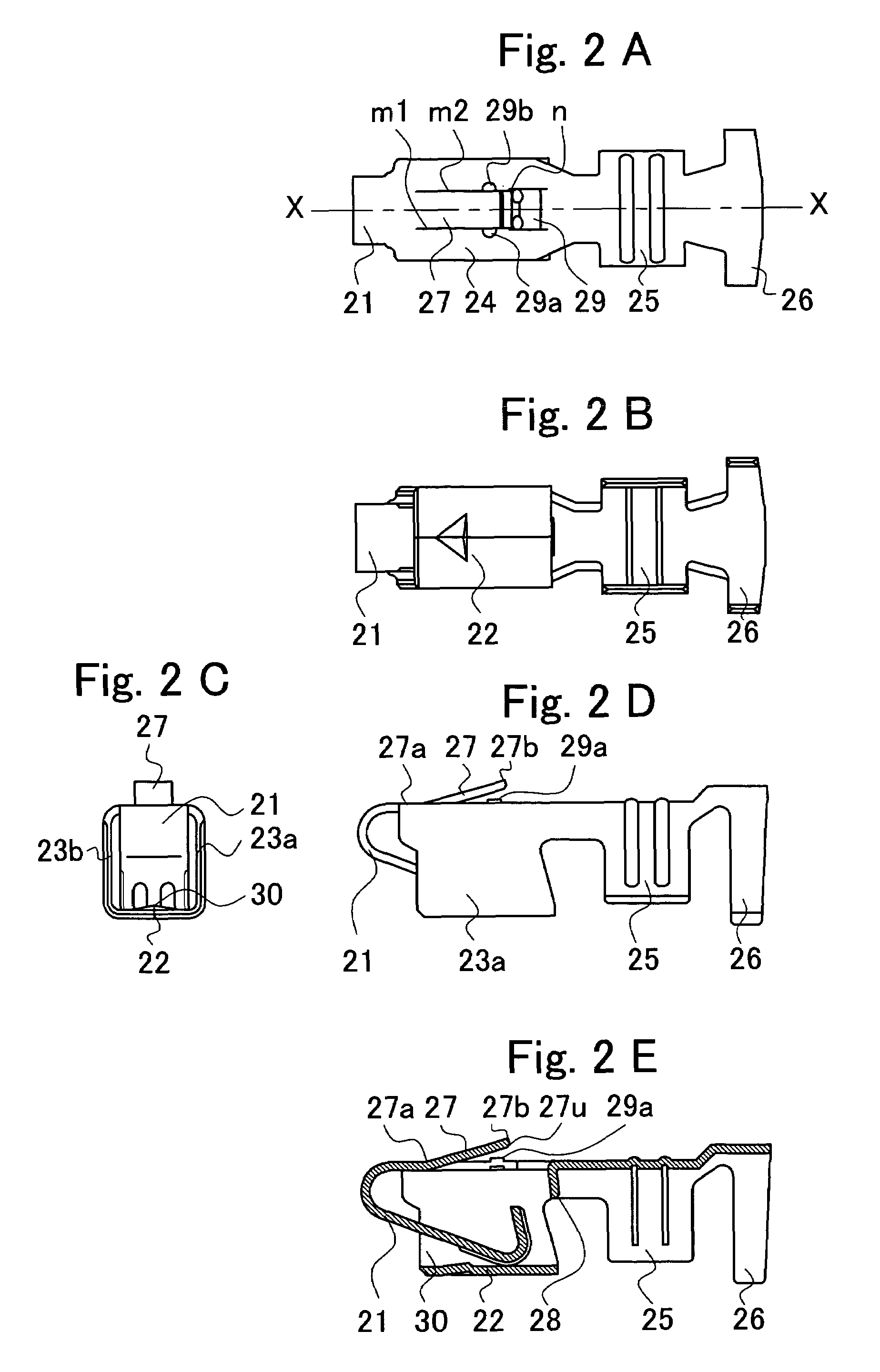
[0041]FIG. 2A is a plan view of the socket contact body 10; FIG. 2B is a bottom view; FIG. 2C is a front view; FIG. 2D is a side view; and FIG. 2E is a cross-sectional view showing a case in which the socket contact body 10 is cut along the line X-X in FIG. 2A. The socket contact body 10 includes a contact portion 11 which comes into contact with a contact (not shown) of an opposite male contact, a crimp terminated portion 12 for crimp terminating and retaining an electric cable 13, and an engaging portion 14 provided between the contact portion 11 and the crimp terminated portion 12.

[0042]The socket contact body 10 is formed...

second embodiment

[0068]FIG. 9 is a drawing showing a state in which a connector of tab type (hereinafter referred to as “tab type connector”) 100 according to the invention is inserted into a housing for connector of tab type (hereinafter referred to as “tab type housing”) 103. The tab type connector 100 includes a contact of tab type (hereinafter, referred to as “tab type contact”) 102, and the tab type housing 103. The tab type contact 102 includes an electric cable 113, and a tab type contact body 110 connected to the electric cable 113.

[0069]The tab type contact body 110 is formed by cutting out and bending a sheet of titan-copper metal plate, which is capable of used under the high temperature conditions in the order of 100 to 200° C. The tab type contact body110 includes a contact portion 111 having a contact plate 122, a crimp terminating portion 112 for crimp terminating and retaining the electric cable 113, and an engaging portion 114 provided between the contact portion 111 and the crimp t...


PUM


Abstract

A connector having a compact engagement structure providing a high retaining force is provided. A shoulder is provided on an inner wall of a housing for storing a contact. The shoulder is inclined so that a distal end thereof projects toward a first end of the housing with respect to a proximal end thereof. An engaging piece which engages the shoulder is provided on an engaging portion of a contact body. An inner edge of a distal end of the engaging piece is chamfered. The contact is inserted into a storage chamber of the housing from a second end of the housing, and the engaging piece smoothly lifts from the distal end of the shoulder to the proximal end. Accordingly, the contact is retained by the housing with a high retaining force.

Description

CROSS-REFERENCE TO RELATED APPLICATIONS[0001]This application is based upon and claims the benefit of priority from Japanese Patent application No. 2004-071578 filed on Mar. 12, 2004, the entire contents of which is incorporated herein by reference.FIELD OF THE INVENTION[0002]The present invention relates to a connector including a contact provided with an engaging piece to be engaged with a shoulder formed on the inner wall of a housing so as to be retained in the housing.RELATED ART[0003]In the related art, a connector having a contact provided with a contact portion that comes into contact with a contact of an opposite connector and a housing for retaining the contact is known as a connector for connecting electric equipment. In such a connector, a contact body formed of conductive material such as a metal plate is fixed to the end of an electric cable covered by an insulating material, and is retained in the insulative housing. The contact body is provided with an engaging piece...

Claims


Application Information

Patent Timeline
Patent Type & Authority Patents(United States)
IPC IPC(8): H01R13/432H01R13/10H01R13/42H01R13/426H01R13/428H01R13/434H01R43/16
CPCH01R13/03H01R13/432H01R43/16
Inventor KUBO, TSUKASAHORII, TOSHIAKITAKEDA, EIJI
Owner JST MFG CO LTD
Why Eureka
Try Eureka