Band rejection filter with attenuation poles

a band rejection filter and attenuation pole technology, which is applied in the direction of electrolysis components, electrical equipment, waveguides, etc., can solve the problems of increasing the circuit scale, difficult to provide a sufficient attenuation in a frequency range close to the resonance frequency, etc., to reduce the number of resonant circuits, improve the attenuation characteristics of the band rejection filter, and reduce the circuit scale

Inactive Publication Date: 2007-08-14
MITSUBISHI ELECTRIC CORP
View PDF14 Cites 3 Cited by
  • Summary
  • Abstract
  • Description
  • Claims
  • Application Information

AI Technical Summary

Benefits of technology

[0006]The present invention is made in order to solve the above-mentioned problems, and it is therefore an object of the present invention to provide a band rejection filter with attenuation poles that can improve its attenuation characteristics over a desired frequency band, and can reduce the number of resonant circuits included in the band rejection filter, thereby reducing the circuit scale.
[0008]Therefore, the aspect of the present invention offers an advantage of being able to improve the attenuation characteristics of the band rejection filter with attenuation poles over a desired frequency band, and to reduce the number of resonant circuits included in the band rejection filter, thereby reducing the circuit scale of the band rejection filter.
[0010]Therefore, the other aspect of the present invention offers an advantage of being able to improve the attenuation characteristics of the band rejection filter with attenuation poles over a desired frequency band, and to reduce the number of resonant circuits included in the band rejection filter, thereby reducing the circuit scale of the band rejection filter.

Problems solved by technology

A problem with the conventional band rejection filter mentioned above is that in some cases the number of series resonant circuits required to obtain a desired attenuation in a certain frequency band has to be increased and therefore the circuit scale has to be increased.
Another problem is that a so-called attenuation pole that provides a maximum attenuation is always formed only at the resonance frequency of the plurality of resonant circuits, and it is therefore difficult to provide a sufficient attenuation in a frequency range of frequencies close to the resonance frequency.

Method used


Image

  • Band rejection filter with attenuation poles
  • Band rejection filter with attenuation poles
  • Band rejection filter with attenuation poles

Examples


embodiment 1

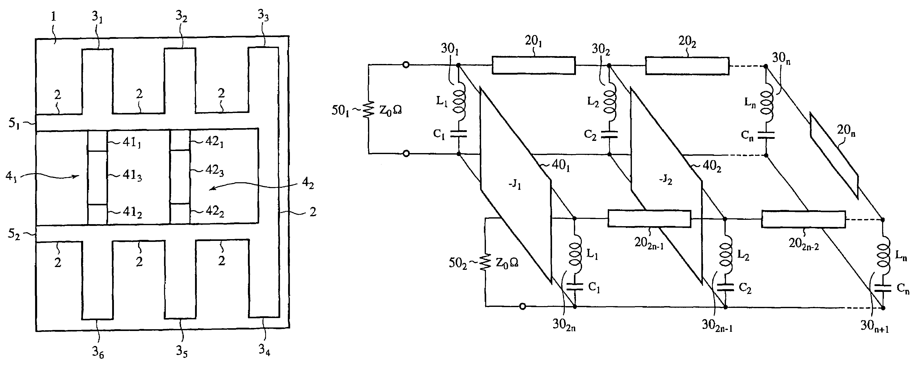
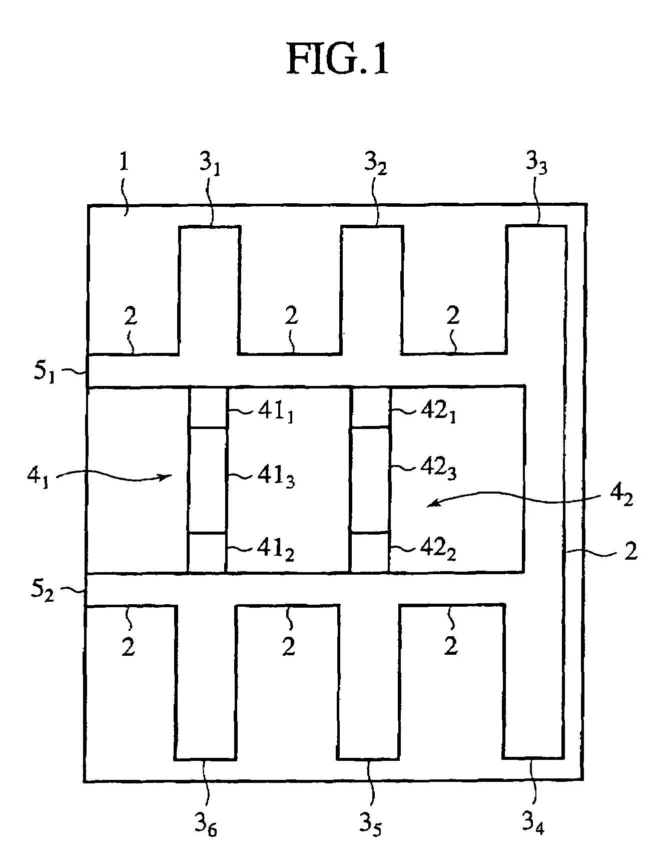
[0024]FIG. 1 is a plan view showing the structure of a band rejection filter with attenuation poles in accordance with embodiment 1 of the present invention. The band rejection filter with attenuation poles includes a transmission line 2 and a plurality of open-ended stubs 31 to 36, each of which is formed of a microstrip line on a dielectric substrate 1, and jump-coupling circuits 41 and 42 formed on the dielectric substrate 1.

[0025]The transmission line 2 is formed of two parallel line segment patterns having ends connected to each other and other ends that are open. The open ends of the transmission line 2 are used as input / output terminals 51 and 52.

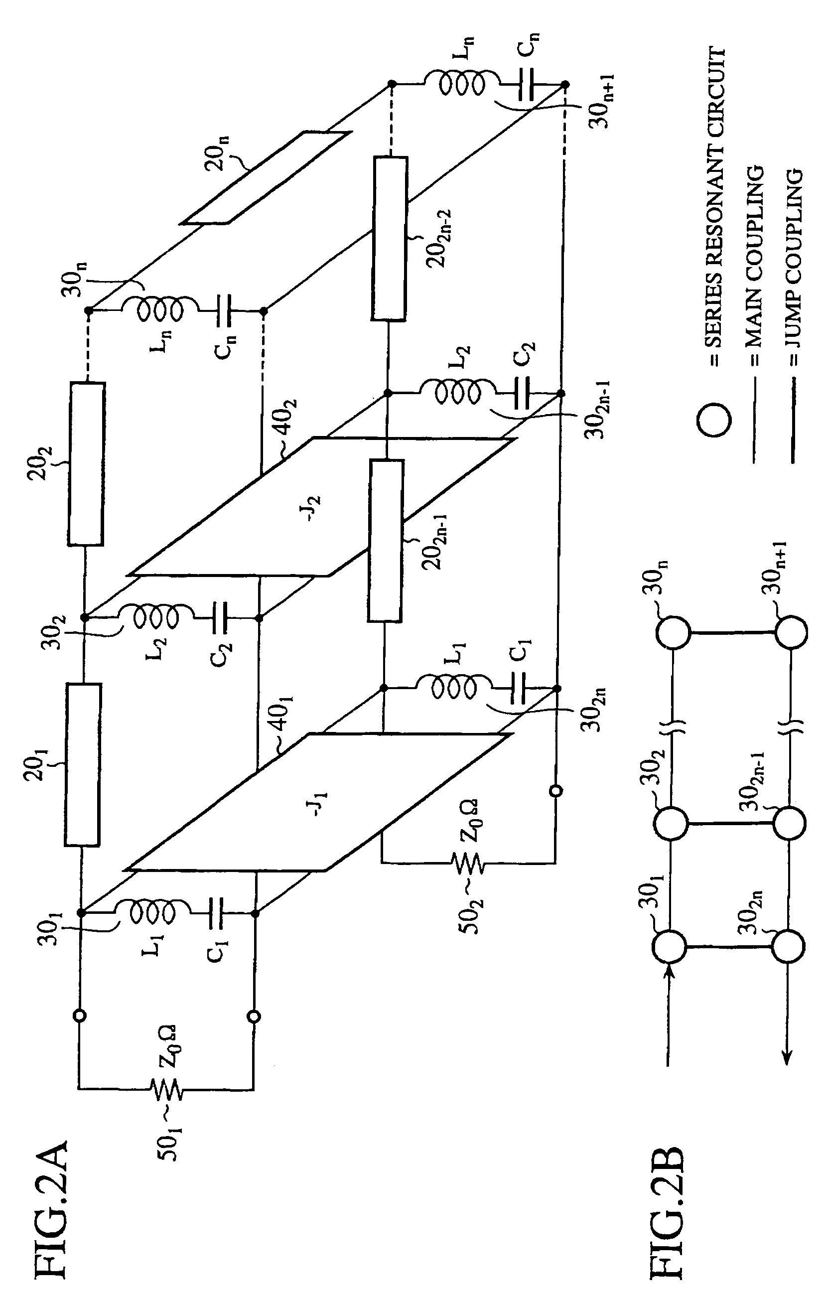
[0026]Each of the plurality of open-ended stubs 31 to 36 functions as a series resonant circuit. Each of the plurality of open-ended stubs 31 to 36 has a length equal to the one-quarter wavelength at the resonance frequency of the series resonant circuit, and is projecting to outside from the transmission line 2. In accordance with t...

embodiment 2

[0039]A band rejection filter with attenuation poles according to embodiment 2 of the present invention employs jump-coupling circuits in each of which a high impedance line, a low impedance line, and another high impedance line are connected in series, instead of the jump-coupling circuits according to embodiment 1.

[0040]FIG. 5 is a plan view showing the structure of the band rejection filter with attenuation poles in accordance with this embodiment 2. The same components as those of embodiment 1 or like components are designated by the same reference numerals as shown in embodiment 1, and therefore the explanation of those components will be omitted hereafter.

[0041]A first jump-coupling circuit 41 includes a high impedance line 431, a low impedance line 433, and another high impedance line 432 that are connected in series. The two high impedance lines 431 and 432 have their respective bent portions that are formed so that their impedances are increased, and each of them is formed ...

embodiment 3

[0046]A band rejection filter with attenuation poles according to embodiment 3 of the present invention employs jump-coupling circuits in each of which a microstrip line having a length sufficiently shorter than the wavelength at the resonance frequency of a plurality of series resonant circuits, a capacitor, and another microstrip line having a length sufficiently shorter than the wavelength at the resonance frequency of the plurality of series resonant circuits are connected in series, instead of the jump-coupling circuits according to embodiment 1.

[0047]FIG. 6 is a plan view showing the structure of the band rejection filter with attenuation poles in accordance with this embodiment 3. The same components as those of embodiment 1 or like components are designated by the same reference numerals as shown in embodiment 1, and therefore the explanation of those components will be omitted hereafter.

[0048]A first jump-coupling circuit 41 is constructed of a microstrip line 451, a capaci...


PUM


Abstract

A band rejection filter with attenuation poles includes a plurality of series resonant circuits having end terminals connected in common and other end terminals connected in series via a plurality of transmission lines each having a length that is an odd multiple of about the one-quarter wavelength at the resonance frequency of the plurality of series resonant circuits, and a jump-coupling circuit for roughly coupling two of the plurality of series resonant circuits, which are not adjacent to each other, to each other.

Description

BACKGROUND OF THE INVENTION[0001]1. Field of the Invention[0002]The present invention relates to a band rejection filter with attenuation poles that is provided with two or more resonant circuits.[0003]2. Description of Related Art[0004]Conventionally, band rejection filters provided with two or more resonant circuits are known (for example, refer to “Microwave Filters, Impedance-Matching Networks, and Coupling Structures”, G. Matthaei, et al., Artech House Publishers, 1980, pp. 735). In general, a band rejection filter is provided with two or more series resonant circuits 200 connected in series via a transmission line 201, as shown in FIG. 11. The transmission line 201 is the one that has a length equal to the one-quarter wavelength at the resonance frequency of the two or more series resonant circuits 200. The band rejection filter is also provided with an input / output terminal 203 having an impedance Zo.[0005]Since the electric nodes of each series resonant circuit 200 are elect...

Claims


Application Information

Patent Timeline
Patent Type & Authority Patents(United States)
IPC IPC(8): H01P1/20H01P1/203H01P1/207H01P1/205H01P1/208
CPCH01P1/20309H01P1/2039H01P1/2088
Inventor UCHIDA, HIROMITSUMIYAZAKI, MORIYASUIMAI, YOSHIHIKOUMEMURA, NORIONAKAYAMA, JUNKOKAMINO, HIROTAKA
Owner MITSUBISHI ELECTRIC CORP
Why Eureka
Try Eureka