SDMA system using MU-SIMO for the uplink and MU-MISO for the downlink

a technology of sdma and uplink, applied in data switching networks, frequency-division multiplexes, instruments, etc., can solve problems such as more difficult problems than just resolving m1 sources

Active Publication Date: 2007-08-14
HEWLETT-PACKARD ENTERPRISE DEV LP
View PDF10 Cites 9 Cited by
  • Summary
  • Abstract
  • Description
  • Claims
  • Application Information

AI Technical Summary

Problems solved by technology

The problem is more difficult than just resolving the m−1 sources, because an additional number of interference sources or interferers need to be rejected and noise needs to be filtered out.

Method used


Image

  • SDMA system using MU-SIMO for the uplink and MU-MISO for the downlink
  • SDMA system using MU-SIMO for the uplink and MU-MISO for the downlink
  • SDMA system using MU-SIMO for the uplink and MU-MISO for the downlink

Examples


Embodiment Construction

[0012]The following detailed description is made with reference to the figures. Preferred embodiments are described to illustrate the present invention, not to limit its scope, which is defined by the claims. Those of ordinary skill in the art will recognize a variety of equivalent variations on the description that follows.

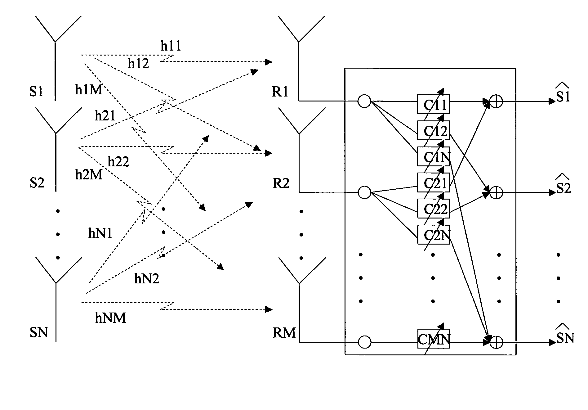
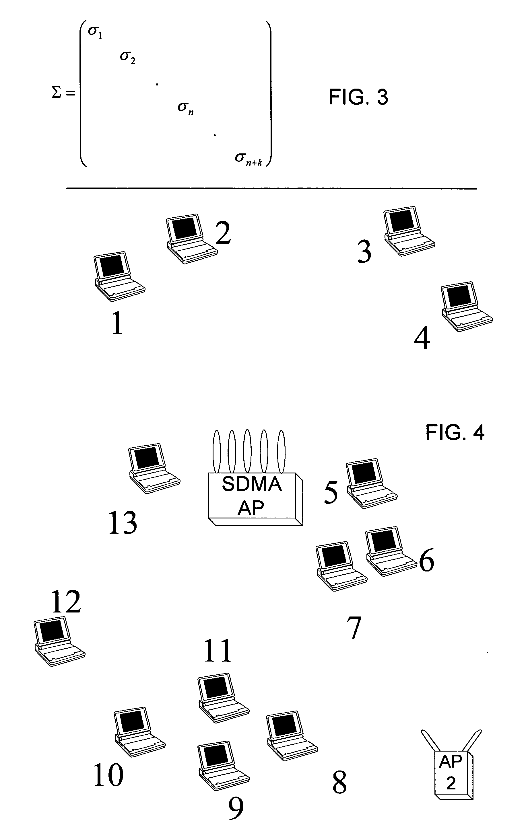
[0013]One application of SDMA to a multi-user wireless system such as a WLAN is to communicate with two or more clients using the same frequency and transmission time, whether the frequency and time are determined by TDMA, CDMA or other allocation strategy. Reusing a channel (communicating on the same frequency band and time instance) is possible when there is sufficient spatial separation between the clients and the base station antennas.

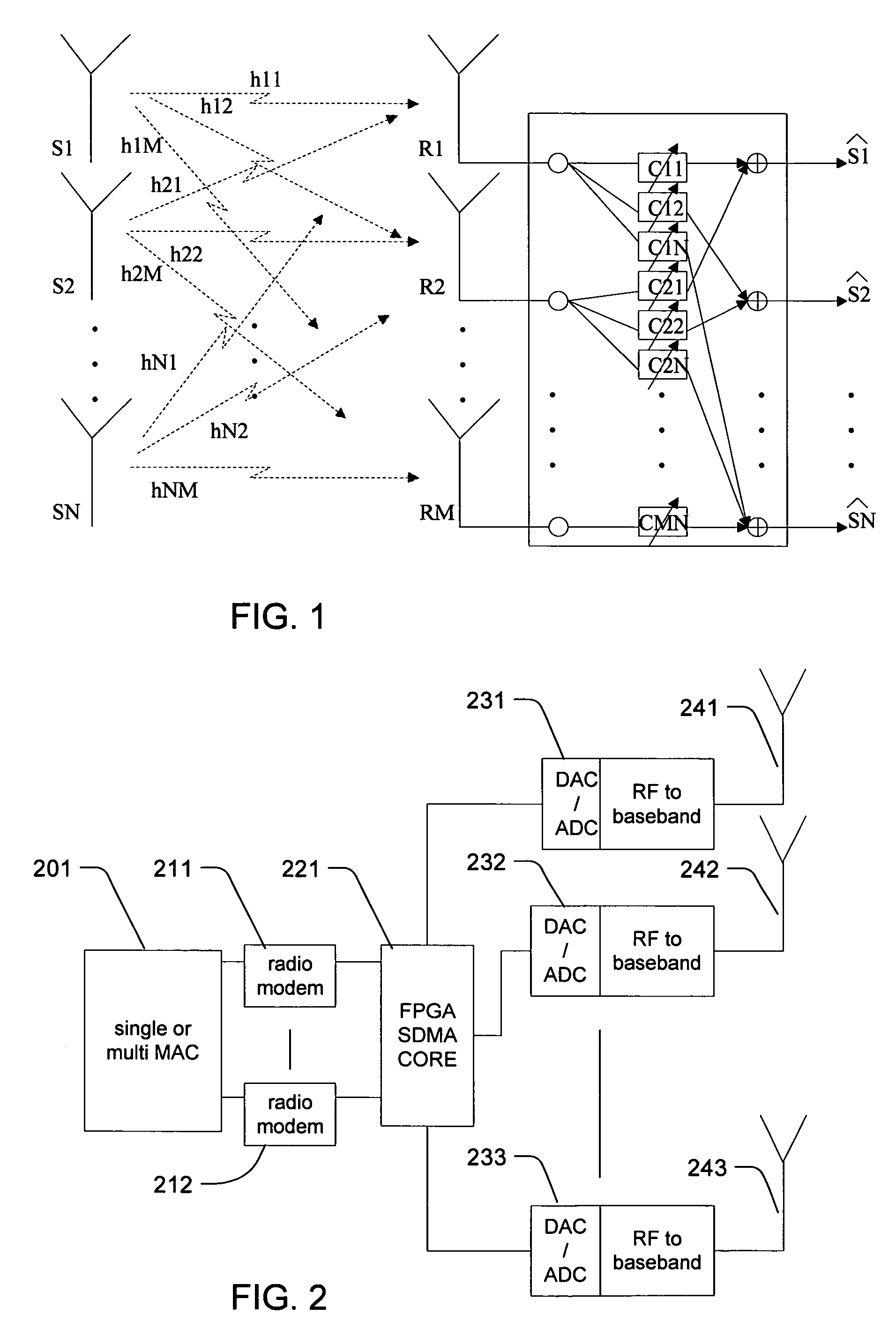
[0014]To reuse channels, application of a MU-SIMO strategy for the uplink and a MU-MISO strategy for the downlink is proposed. MU-SIMO refers to multiple user, single input (at the mobile unit) multiple output (at the base stati...


PUM


Abstract

The present invention relates to multiple antenna wireless access points that multiplex signals by spatial division. In particular, it relates to grouping clients of the access point for spatial division multiplexing. Particular aspects of the present invention are described in the claims, specification and drawings.

Description

BACKGROUND OF THE INVENTION[0001]The present invention relates to multiple antenna wireless access points that multiplex signals by spatial division. In particular, it relates to grouping clients of the access point for spatial division multiplexing.[0002]Wireless LAN (WLAN) access points are a popular product category. As the number of clients that desire service from an access point increases, one strategy for increasing the number of clients served is spatial division multiplexing (SDMA). Spatial diversity involves the use of multiple antennas sufficiently well-separated at the receiver and / or the transmitter that the individual transmission paths experience effectively independent fading. Juha Heiskala and John Terry, OFDM Wireless LANs: A theoretical and Practical Guide 2002 p. 131. Some theoretical investigation has been directed to the effectiveness of spatial multiplexing, such as Helmut Bölcskei et al., “On the Capacity of OFDM-Based Spatial Multiplexing Systems”, IEEE Tran...

Claims


Application Information

Patent Timeline
Patent Type & Authority Patents(United States)
IPC IPC(8): H04Q7/00H01Q25/00H04B7/06H04B7/08H04L12/28H04W16/10
CPCH01Q25/00H04B7/0691H04B7/0874H04W16/10
Inventor VAN ERVEN, NIELS
Owner HEWLETT-PACKARD ENTERPRISE DEV LP
Why Eureka
Try Eureka