X-ray source assembly having enhanced output stability using tube power adjustments and remote calibration

a technology of x-ray source and output stability, applied in the field of x-ray sources, can solve the problems of large range of misalignment between the x-ray diverging from the anode, large output power intensity uneven position of the x-ray source, so as to enhance the stability of the x-ray spot or x-ray beam position, and enhance the effect of output stability

Inactive Publication Date: 2007-08-14
X-RAY OPTICAL SYSTEM INC
View PDF30 Cites 55 Cited by
  • Summary
  • Abstract
  • Description
  • Claims
  • Application Information

AI Technical Summary

Benefits of technology

[0009]The use of e-beam impingement upon an anode to generate x-rays, in the x-ray sources described above, can generate an amount of heat sufficient to cause thermal expansion of the elements which support and position the x-ray tube within the x-ray source. This thermal expansion can cause misalignment between the x-rays diverging from the anode and, e.g., the element that serves to control the direction of the x-rays. As a result, operating an x-ray source at different powers may lead to a range of misalignments between the diverging x-rays and the focusing optic. This misalignment could cause the output power intensity of the x-ray source to vary widely. Misalignment could also cause changes in x-ray output spot or x-ray beam position for some types of beam controlling elements, e.g., for pinholes or single reflection mirrors. Thus, in one aspect, provided herein is an x-ray source assembly having enhanced output stability over a range of operating power levels, as well as enhanced x-ray spot or x-ray beam position stability. More particularly, an x-ray source assembly in accordance with an aspect of the present invention provides an x-ray beam output intensity which can be maintained relatively constant notwithstanding variation in one or more operating conditions of the x-ray source, such as anode power level, housing temperature and ambient temperature about the assembly.

Problems solved by technology

This thermal expansion can cause misalignment between the x-rays diverging from the anode and, e.g., the element that serves to control the direction of the x-rays.
As a result, operating an x-ray source at different powers may lead to a range of misalignments between the diverging x-rays and the focusing optic.
This misalignment could cause the output power intensity of the x-ray source to vary widely.

Method used


Image

  • X-ray source assembly having enhanced output stability using tube power adjustments and remote calibration
  • X-ray source assembly having enhanced output stability using tube power adjustments and remote calibration
  • X-ray source assembly having enhanced output stability using tube power adjustments and remote calibration

Examples


Embodiment Construction

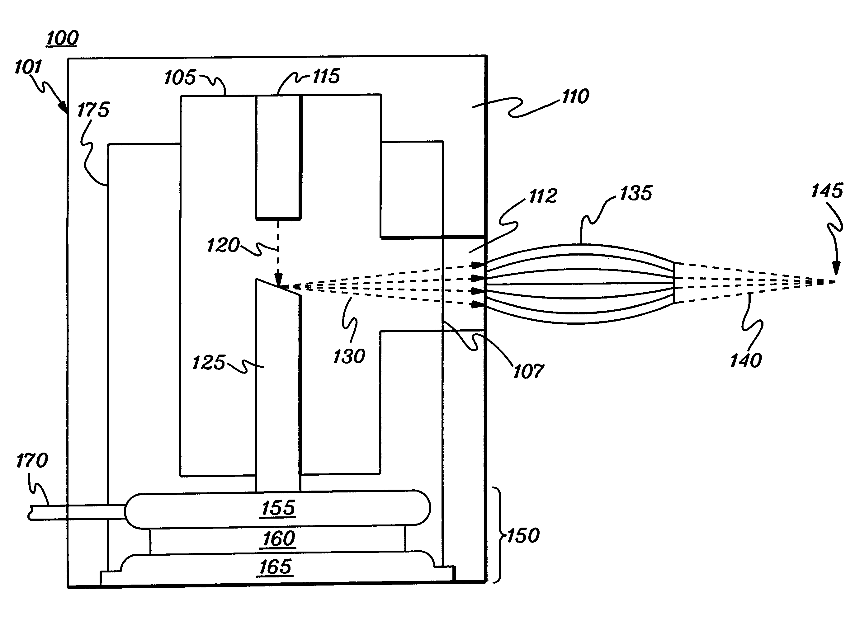
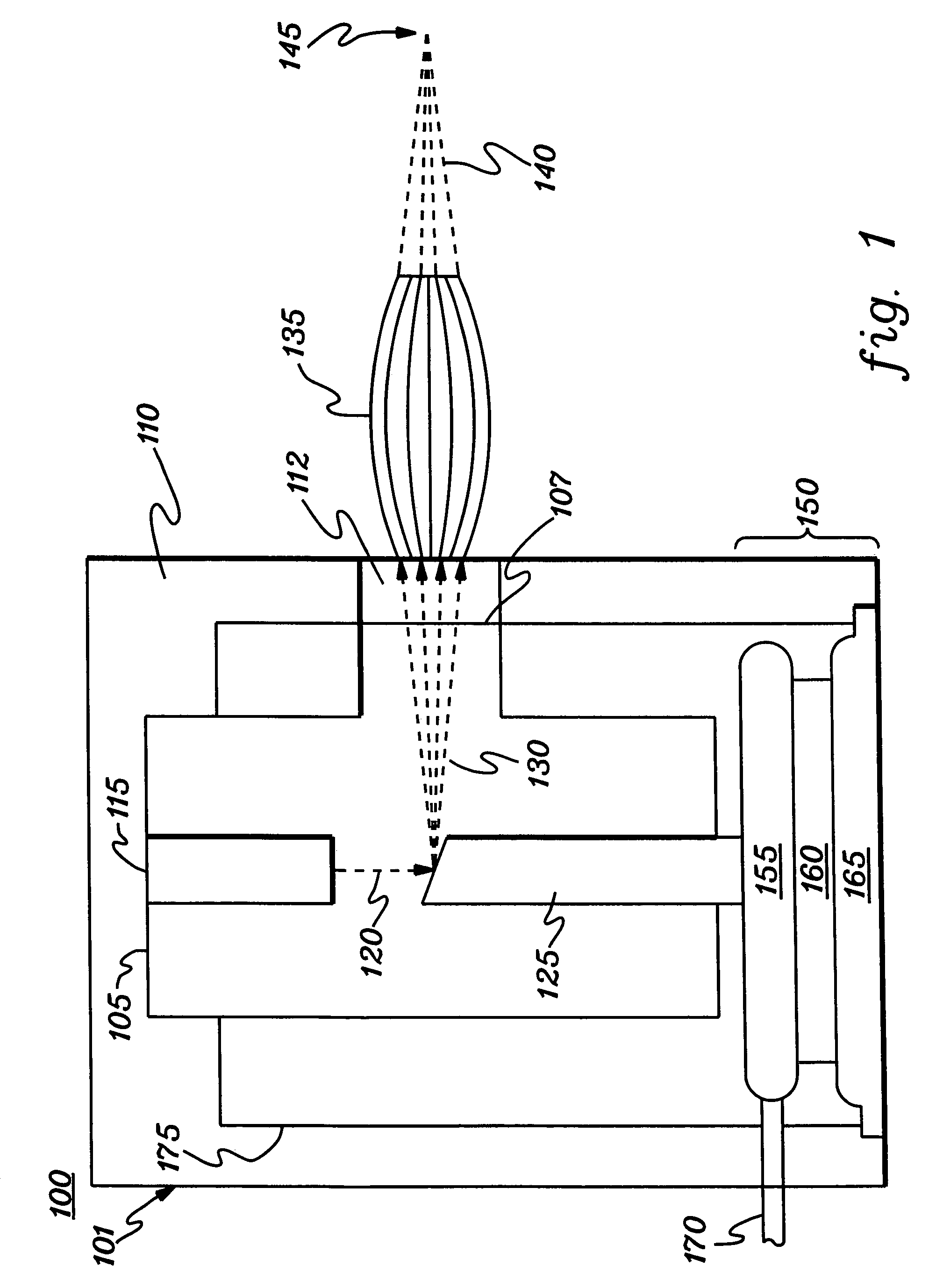
[0030]As generally discussed above, the present invention provides in one aspect an x-ray source assembly providing, for example, a focused x-ray beam or a collimated x-ray beam, and having a stable output over a range of operating conditions. This stable output is obtained via a control system which controls, in one aspect, power supplied to the source notwithstanding a change in one or more of the operating conditions.

[0031]The control system employs one or more actuators which can effect the necessary changes. For example, one actuator might comprise a power actuator which (in cooperation with a power supply) changes the power supplied to the tube; a temperature actuator which provides heating / cooling of the anode to effect adjustments in the anode source spot location relative to the output structure; or a mechanical actuator which would physically adjust position of either the anode source spot or the output structure as needed. Still another actuator might electrostatically or...


PUM

PropertyMeasurementUnit
thicknessaaaaaaaaaa
thicknessaaaaaaaaaa
displacementaaaaaaaaaa

Abstract

An x-ray source assembly includes an anode having a spot upon which electrons impinge based on power level supplied to the assembly, and an optic coupled to receive divergent x-rays generated at the spot and transmit output x-rays from the assembly. A control system is provided for maintaining intensity of the output x-rays dynamically during operation of the x-ray source assembly, notwithstanding a change in at least one operating condition of the x-ray source assembly, by changing the power level supplied to the assembly. The control system may include at least one actuator for effecting the change in the power level supplied to the assembly, by, e.g., controlling a power supply associated with the assembly. The control system may also change the temperature and / or the position of the anode to maintain the output intensity.

Description

RELATED APPLICATION INFORMATION [0001]This application is a continuation of PCT Application PCT / US04 / 25113 filed Aug. 4, 2004, and published under the PCT Articles in English as WO 2005 / 018289 A2 on Feb. 24, 2005. PCT / US2004 / 025113 claimed priority to U.S. Provisional Application No. 60 / 492,353, filed Aug. 4, 2003. The entire disclosures of PCT / US2004 / 025113 and U.S. Ser. No. 60 / 492,353 are incorporated herein by reference in their entirety. In addition, this application contains subject matter which is related to the subject matter of the following applications, which are hereby incorporated herein by reference in their entirety:[0002]“X-RAY TUBE AND METHOD AND APPARATUS FOR ANALYZING FLUID STREAMS USING X-RAYS,” by Radley et al., U.S. Ser. No. 60 / 336,584, filed Dec. 4, 2001 and perfected as PCT application PCT / US02 / 38792;[0003]“X-RAY SOURCE ASSEMBLY HAVING ENHANCED OUTPUT STABILITY” by Radley et al., U.S. Ser. No. 60 / 398,965, filed Jul. 26, 2002 and perfected as PCT application PC...

Claims


Application Information

Patent Timeline
Patent Type & Authority Patents(United States)
IPC IPC(8): H05G1/26G01N23/223H05G1/36
CPCH05G1/36H05G1/025G21K2201/06H01J2235/1291
Inventor RADLEY, IANMOORE, MICHAEL D.FITZGERALD, MARK
Owner X-RAY OPTICAL SYSTEM INC
Why Eureka
Try Eureka