Adjustable pulse width control power supply conversion method and device

A technology of power conversion and pulse width control, which is applied in the direction of output power conversion devices, electrical components, pulse generation, etc., can solve the problems of enlarged output voltage waveform, achieve the improvement of output voltage waveform, good output stability, and reduce The effect of power loss

Active Publication Date: 2010-11-17
ADVANCED ANALOG TECH INC
View PDF0 Cites 14 Cited by
  • Summary
  • Abstract
  • Description
  • Claims
  • Application Information

AI Technical Summary

Problems solved by technology

[0006] However, it is known that the power conversion device that switches from PWM mode to PFM mode at light load, because the switching voltage difference, load size, and external components (inductor, capacitor) are ignored when operating in PFM mode, the pulse width of the pulse control signal is uniform. is a fixed value, so in

Method used


Image

  • Adjustable pulse width control power supply conversion method and device
  • Adjustable pulse width control power supply conversion method and device
  • Adjustable pulse width control power supply conversion method and device

Examples


Embodiment Construction

[0070] The specific embodiments adopted by the present invention will be further described through the following embodiments and accompanying drawings.

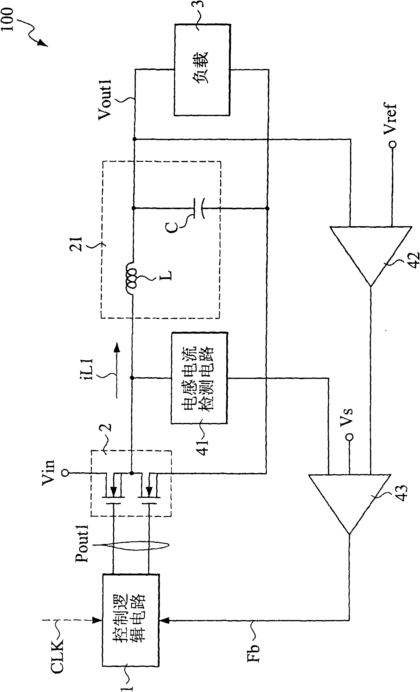
[0071] Please also see Figure 4 and Figure 5 , the control circuit of the power conversion device 100a with adjustable pulse width control in the present invention includes an adjustable pulse width PFM control circuit 11, a PWM control circuit 12, a PWM / PFM switching unit 13, a switch circuit 2 and a load status detection Circuit 5.

[0072] The adjustable pulse width PFM control circuit 11 is connected to the PWM control circuit 12 through a PWM / PFM switching unit 13 . Figure 5 As shown, the adjustable pulse width PFM control circuit 11 mainly includes a control logic unit 111, which is connected to a storage unit 112, and the storage unit 112 stores an initial pulse width value W, a pulse width increment series dW and a correction factor The parameter N enables the control logic unit 111 to control a pulse generator ...


PUM


Abstract

The invention relates to an adjustable pulse width control power supply conversion method and device, wherein the device comprises an adjustable pulse width PFM control circuit, a PWM control circuit, a PWM/PFM switching unit, a switch circuit and a load state detection circuit; and before a PWM mode is switched into a PFM mode, the grade is increased by preset pulse width, the pulse width of a PFM control signal of a sequence is gradually adjusted from low to high sequentially to an optimum pulse width valve, and then the output voltage is supplied to the load by the PFM mode, so that the output voltage wave form when in the PFM mode can be improved, and the output stability of the power supply conversion device is better.

Description

technical field [0001] The invention relates to the design of a power conversion device, in particular to a power conversion method and device with adjustable pulse width control. Background technique [0002] In increasingly complex electronic and computer system devices, power conversion devices play a pivotal role. refer to figure 1 As shown, it is a control circuit diagram showing a known power conversion device. The known power conversion device 100 is mainly composed of a control logic circuit 1 that generates a sequence of pulse control signals Pout1 to control the switch circuit 2, so that the semiconductor elements (such as MOSFETs) in the switch circuit 2 are turned on or off, and then passed through a filter circuit 21. The input voltage source Vin is converted into the output voltage Vout1 required by the load 3 . [0003] The control logic circuit 1 generally adopts pulse width modulation (Pulse Width Modulation, PWM) mode for output control. The characterist...

Claims


Application Information

Patent Timeline
IPC IPC(8): H02M1/00H03K3/017
Inventor 谢顺安林俞伸
Owner ADVANCED ANALOG TECH INC
Why Eureka
Try Eureka