Hydro-viscous speed regulation device

A fluid-viscous, speed-regulating technology, applied in the direction of fluid clutches, clutches, mechanical equipment, etc., can solve problems such as eccentric wear of friction pairs, achieve the effects of shortening the axial distance, saving costs, and improving the uniformity of the oil film

Inactive Publication Date: 2013-02-06
ZHEJIANG UNIV
View PDF12 Cites 16 Cited by
  • Summary
  • Abstract
  • Description
  • Claims
  • Application Information

AI Technical Summary

Problems solved by technology

[0005] The purpose of the present invention is to provide a new liquid-viscous speed-regulating device for the eccentric wear of the friction p

Method used


Image

  • Hydro-viscous speed regulation device
  • Hydro-viscous speed regulation device
  • Hydro-viscous speed regulation device

Examples


Embodiment approach

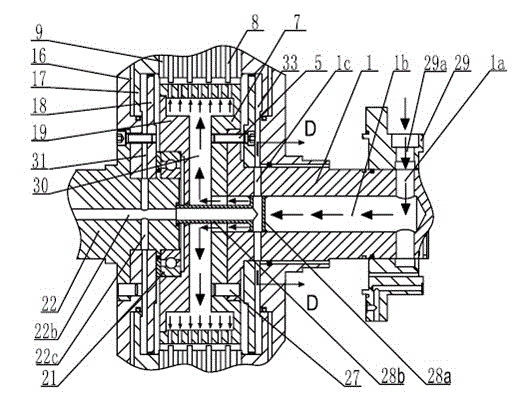
[0037] Further, as the second embodiment of the present invention, the transmission mechanism is the same as that of the first embodiment of the present invention, and the control mechanism still adopts a single piston structure, but the piston cylinder (ie, the first piston cylinder) adopts Figure 8 with Picture 9 The structure shown, thereby obtaining better technical effects. Specifically, such as Figure 8 with Picture 9 As shown, the driven disk 16 and the first piston top disk 18 are respectively fixedly connected to the driven shaft 22, thereby forming a piston cylinder block (that is, the cylinder of the first piston cylinder) between the driven disk 16 and the first piston top disk 18 Body), the first piston 17 is placed in the piston cylinder and partitions the piston cylinder into a first spring displacement cavity 32 and a first working oil cavity 31 that are not connected to each other. Among them, a first spring displacement chamber 32 is formed between the firs...


PUM


Abstract

The invention discloses a hydro-viscous speed regulation device which comprises a transmission mechanism, a control mechanism, a drive shaft transparent cover and a driven shaft transparent cover, and the hydro-viscous speed regulation device further comprises a gear sleeve and a support base, wherein the gear sleeve is fixedly connected with a drive shaft and is located at the end part of a power output end of the drive shaft, and an initiative friction plate is arranged on the gear sleeve; the support base is connected with a driven shaft and can rotate opposite to the driven shaft; the support base is located at the end part of a power input end of the driven shaft, the support base is connected with the gear sleeve, the support base and the gear sleeve enclose to form a lubricating oil cavity together, an axial oil duct of the drive shaft is communicated with the lubricating oil cavity, an axial oil duct of the driven shaft is not communicated with the lubricating oil cavity, and the lubricating oil can go between the initiative friction plate and a passive friction plate; and a working oil cavity of a piston cylinder is communicated with a second radial oil duct. According to the invention, the drive shaft is changed into a split type from an integral type to further improve a lubricating oil duct, so that the problem of eccentric wear of friction plates in the prior art is solved fundamentally.

Description

Technical field [0001] The invention relates to a liquid viscous speed regulating device, which can be applied to the speed regulating and energy saving of various fans, water pumps and other devices in high energy consumption industries such as electric power, petrochemical, metallurgy and coal. Background technique [0002] The liquid-viscous speed-regulating clutch is a kind of liquid-viscous speed-regulating device, which is based on Newton's internal friction law, which relies on liquid viscosity and oil film shear to transmit power, and adjusts the speed by changing the oil film gap. In the 1970s, the Philadelphia Gear Company of the United States took the lead in researching and developing liquid viscosity speed control technology products. Professor Wei Chenguan of Beijing Institute of Technology in my country successfully developed a new type of liquid viscosity speed control device based on electro-hydraulic proportional control technology on the basis of introducing Ame...

Claims


Application Information

Patent Timeline
IPC IPC(8): F16D35/00
Inventor 龚国芳廖湘平刘毅韩冬杨学兰杨晓霖杨华勇
Owner ZHEJIANG UNIV
Why Eureka
Try Eureka