Image forming apparatus

a technology of forming apparatus and forming tube, which is applied in the direction of electrographic process apparatus, instruments, developers, etc., can solve the problem of no longer having the density of images, and achieve the effect of avoiding wasteful use of developers, short time, and low cos

Active Publication Date: 2007-08-14
BROTHER KOGYO KK
View PDF13 Cites 8 Cited by
  • Summary
  • Abstract
  • Description
  • Claims
  • Application Information

AI Technical Summary

Benefits of technology

[0008]It is one object of the present invention to provide an image forming apparatus that allows formation of an image with adequate density even if the charged amount per unit mass of the developer is changed.
[0031]The developer may be a polymerized toner. A change in the charged amount per unit mass of the polymerized toner is usually larger than a change in the charged amount per unit mass of a ground toner. Effects on the image density are large if the change in the charged amount is large. Therefore, in a configuration in which the polymerized toner is used as the developer, significantly large effects are generated by adjustment of the developer bias.

Problems solved by technology

Accordingly, an image having appropriate density is no longer obtainable.

Method used


Image

  • Image forming apparatus
  • Image forming apparatus
  • Image forming apparatus

Examples


Embodiment Construction

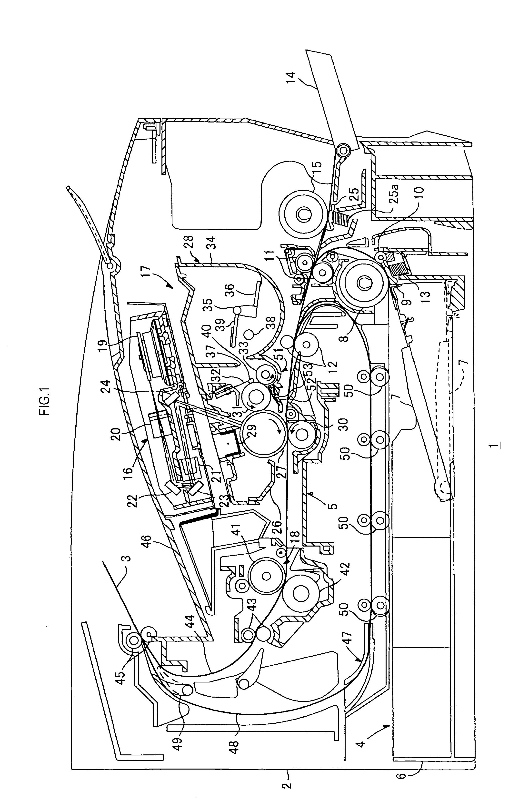
[0052]Referring to FIG. 1, a laser printer 1 of the present embodiment comprises a body casing 2, inside of which a feeder portion 4 and an image forming portion 5 are provided. The feeder portion 4 feeds paper P (not shown), and the image forming portion 5 forms a predetermined image on the fed paper P.

[0053]The feeder portion 4 includes a feed tray 6 detachably attached to a bottom section inside of the body casing 2, a paper pressing plate 7 provided inside of the feed tray 6, a feed roller 8 and a feed pad 9 provided above an end on one side of the feed tray 6, paper powder removing rollers 10 and 11 provided downstream of the feed roller 8 in the conveying direction of the paper P, and a pair of resist rollers 12 provided downstream of the paper powder removing rollers 10 and 11 in the conveying direction of the paper P.

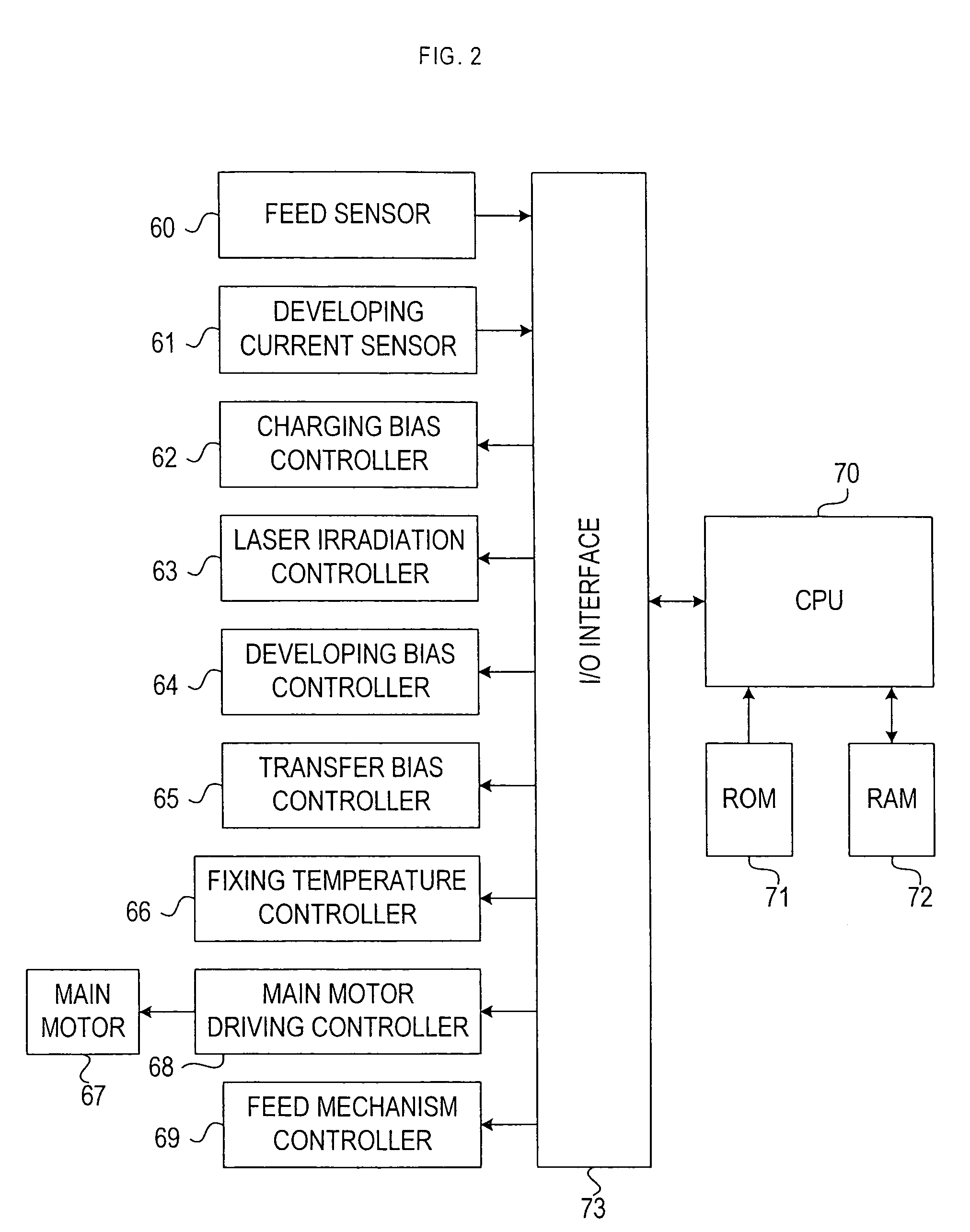
[0054]Furthermore, a feed sensor 60 not shown in FIG. 1 (see FIG. 2), that turns ON when it detects the passing of the paper P, is provided at a position close ...


PUM


Abstract

An image forming apparatus that forms an image having proper density regardless of changes in a charged amount of developer per unit mass is provided. When image data is received in a laser printer, a main motor is driven to rotate a photosensitive drum, etc., and charging bias is applied to a charger to charge the photosensitive drum. Then, paper is fed. Predetermined current detection developing bias is applied to a developing roller for a predetermined period of time. A current value of a developing current during the application is detected. Developing bias applied to the developing roller is calculated so as to keep constant density in the printed image. Particularly, a charged amount of toner per unit mass (Q / M) is calculated from the detected current value. Based on the Q / M, the developing bias is calculated. A print process is performed by applying the developing bias to the developing roller.

Description

BACKGROUND OF THE INVENTION[0001]i) Technical Field of the Invention[0002]This invention relates to an image forming apparatus that forms an image on a recording material using developer.[0003]ii) Description of the Related Art[0004]Conventionally, in an image forming apparatus that forms an image on a recording material using developer, image density is often varied depending on conditions like the use environment and the number of prints. Therefore, there are cases in which desired density can not be obtained.[0005]Unexamined Patent Publication No. 7-140769 discloses an image forming device in which a reference pattern consisting of a toner image for density detection is formed on a photosensitive drum. Based on the detected density of the reference pattern, the optimum developing bias at the time of actual developing is obtained.SUMMARY OF THE INVENTION[0006]Density variation of an image formed using developer is largely affected by a change in charged amount per unit mass of the...

Claims


Application Information

Patent Timeline
Patent Type & Authority Patents(United States)
IPC IPC(8): G03G15/00G03G9/087G03G15/06G03G15/08G03G21/14
CPCG03G15/06
Inventor YOSHIDA, YUKIMASA
Owner BROTHER KOGYO KK
Why Eureka
Try Eureka