
Windowed thermal ablation probe

Inactive Publication Date: 2007-08-21
RELIEVANT MEDSYST +1
View PDF29 Cites 92 Cited by
  • Summary
  • Abstract
  • Description
  • Claims
  • Application Information

AI Technical Summary

Benefits of technology

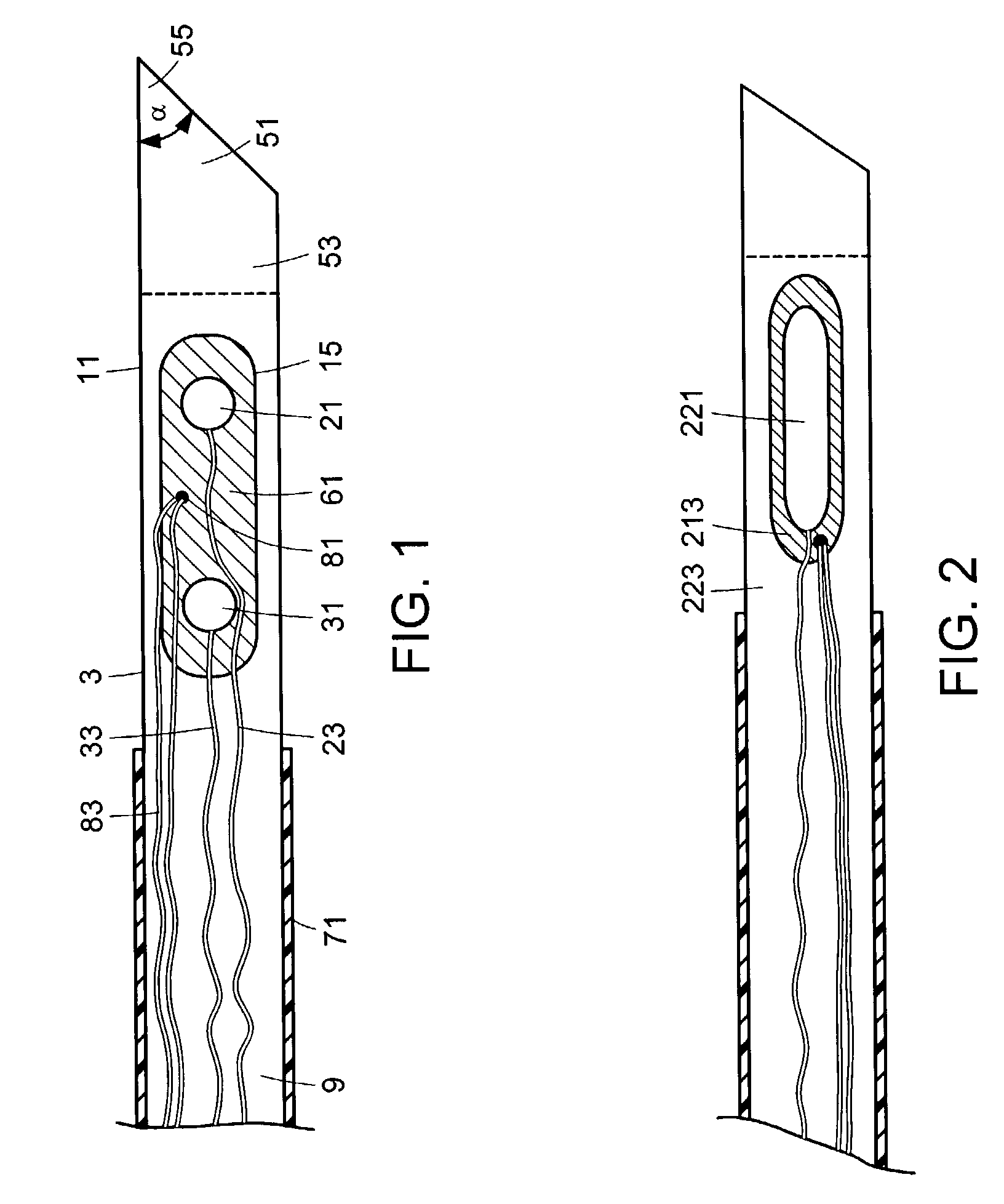
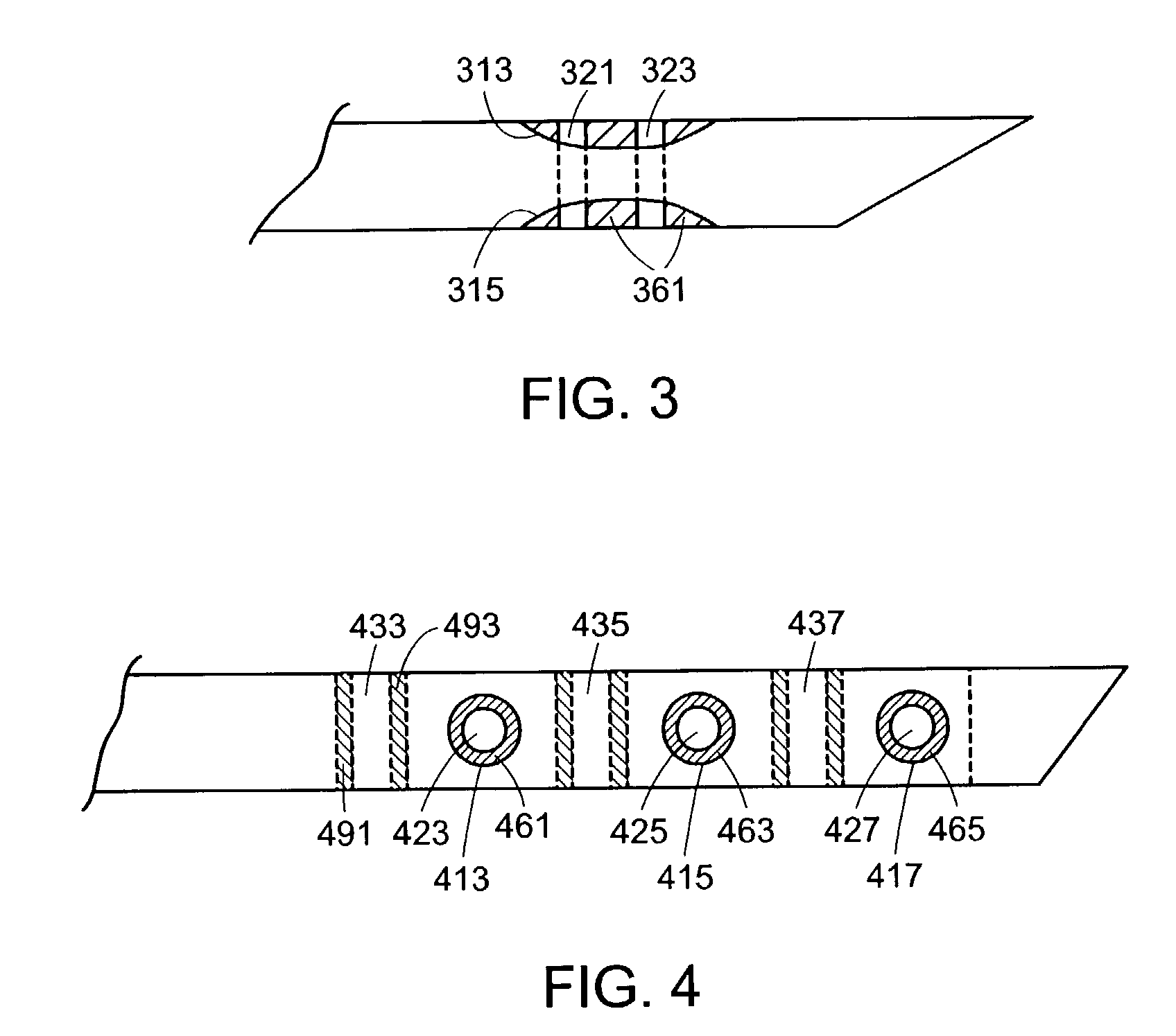
[0012]The present inventors have found that the shaft of a bipolar probe adapted to penetrate bone can be made by simply joining a solid, sharp tip onto a hollow tube. The resulting shaft is of sufficient strength to penetrate the cortical shell of a vertebral body. Furthermore, since the shaft comprises a hollow tube, wires for an electrode can be housed within the tube, thereby allowing a bipolar or sesquipolar configuration. The combination of the ability to penetrate a cortical shell and the ability to provide bipolar or sesquipolar function represents an advance over the conventional technology.
[0017]In some embodiments, a space is provided between the tip and tube for ease of manufacturing.
[0021]In another aspect of the present invention, the present inventors have found that if the tubular portion of the shaft is made of an electrically conductive material and a window is formed in that tubular portion, then a simple and effective probe can be made by electrically insulating the rim of the window and then placing an electrode within the insulated window. This configuration allows the construction of a bipolar electrode having a simple and low cost design.
[0029]In some embodiments, both the return and active electrodes are housed within the same window, thereby further reducing the complexity of the manufacturing process.

Problems solved by technology

However, monopolar approaches require the use of a grounding pad beneath the patient and allows energy to flow from the probe and to dissipate in the surrounding tissue.
Because the path by which the energy flows from a monopolar probe to its corresponding pad is uncontrolled, the energy may undesirably flow through sensitive tissue, such as the spinal cord.
Since this method may cause undesired local muscle or nerve stimulation, it may be difficult or dangerous to operate in sensitive areas of the human body.
Sharkey does not disclose a return and an active electrode located within the same window.
Sharkey does not disclose a window in a conductive shaft.
Sharkey does not disclose a probe having a tip adapted to penetrate bone.
Like Sharkey, Goble does not disclose a return and an active electrode located within the same window, nor a window in a conductive shaft, nor a probe having a tip adapted to penetrate bone.

Method used


Image

  • Windowed thermal ablation probe
  • Windowed thermal ablation probe
  • Windowed thermal ablation probe

Examples


example i

[0179]This prophetic example describes a preferred dual probe embodiment of the present invention.

[0180]First, after induction of an appropriate amount of a local anesthesia, the human patient is placed in a prone position on the table. The C-arm of an X-ray apparatus is positioned so that the X-rays are perpendicular to the axis of the spine. This positioning provides a lateral view of the vertebral body, thereby allowing the surgeon to view the access of the apparatus into the vertebral body.

[0181]Next, the device of the present invention is inserted into the skin at a lateral location so that its distal tip passes posterior to the dorsal nerves located outside the vertebral body.

[0182]Next, the device is advanced interiorly into the vertebral body so that the distal tip bores through the skin, into and through the cortical shell of the vertebral body. The device is advanced until the tip reaches the anterior-posterior midline of the vertebral body.

[0183]Next, the power supply is ...


PUM


Abstract

This invention relates to an electrosurgical device having a hollow shaft, an electrically conductive distal tip that is also adapted for penetrating bone, and an intermediate electrically insulating spacer.

Description

RELATED APPLICATIONS[0001]This application is related to U.S. patent application Ser. No. 10 / 259,689 , filed Sep. 30, 2002, entitled “Novel Device for Advancing a Functional Element Through Tissue”, the specification of which is incorporated by reference.BACKGROUND OF THE INVENTION[0002]In an effort to reduce back pain through early intervention techniques, some investigators have focused upon nerves contained within the vertebral bodies.[0003]For example, PCT Patent Publication No. WO 01 / 0157655 (“Heggeness”) discloses ablating nerves contained within the vertebral body by first boring into the vertebral body with a nerve ablation device, placing the tip of the device in close proximity to the nerve, and then ablating the nerves with the tip. Heggeness discloses numerous devices, such as electricity transmitting probes, as candidate nerve ablation devices. In describing how to use such as probe, Heggeness discloses “raising the temperature of tip 24 such that the intraosseous nerve...

Claims


Application Information

Patent Timeline
IPC IPC(8): A61B18/12A61B18/14
CPCA61B18/1477A61B18/18A61B18/148A61B2018/0044A61B2018/00791A61B2018/1467A61B2018/00071
Inventor SUTTON, JEFFREYRYAN, THOMASPATEL, SAMITPELLEGRINO, RICHARD
Owner RELIEVANT MEDSYST
Learn More