Thermal enhanced package for block mold assembly

a technology of molded plastic and block molds, applied in the direction of solid-state devices, electric devices, basic electric elements, etc., can solve the problems of poor thermal conductivity of molding compound, prone to manufacturing defects in the molding process, and low level of automation of the molding process for assembly of lower-cost molded plastic packages

Inactive Publication Date: 2007-08-21
ADVANCED INTERCONNECT TECH LTD
View PDF18 Cites 101 Cited by
  • Summary
  • Abstract
  • Description
  • Claims
  • Application Information

AI Technical Summary

Benefits of technology

[0013]The above-described and other drawbacks and deficiencies of the prior art are overcome or alleviated by a device comprising: a substrate having first and second generally opposite surfaces, the substrate first surface having a plurality of bond sites disposed thereon; a die having first and second generally opposite surfaces parallel to the substrate first and second surfaces, the die first surface having a plurality of I / O pads disposed thereon, the I / O pads being electrically connected to the bond sites; a molding compound encapsulating the die and at least the first surface of the substrate; and a heat spreader at least partially embedded in the molding compound. The heat spreader has a peripheral cut edge portion aligned with and not recessed from associated peripheral cut edge portions of the substrate and molding compound.

Problems solved by technology

Problematically, the molding compound is a poor thermal conductor.
Unfortunately, manufacturing methods for packages employing this type of heat spreader have not lent themselves to the high level of automation needed for assembly of lower cost molded plastic packages.
The use of individual molds for each package is undesirable for certain applications because it makes the molding process prone to manufacturing defects such as misalignment of the individual molds relative to the die and substrate.

Method used


Image

  • Thermal enhanced package for block mold assembly
  • Thermal enhanced package for block mold assembly
  • Thermal enhanced package for block mold assembly

Examples


Embodiment Construction

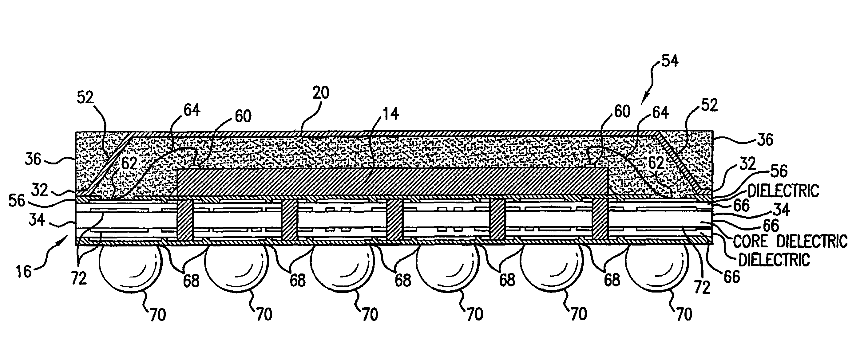
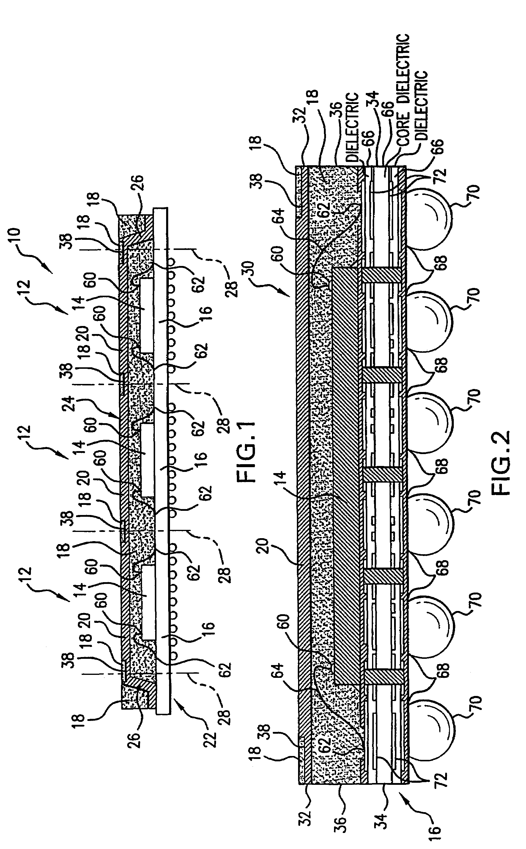
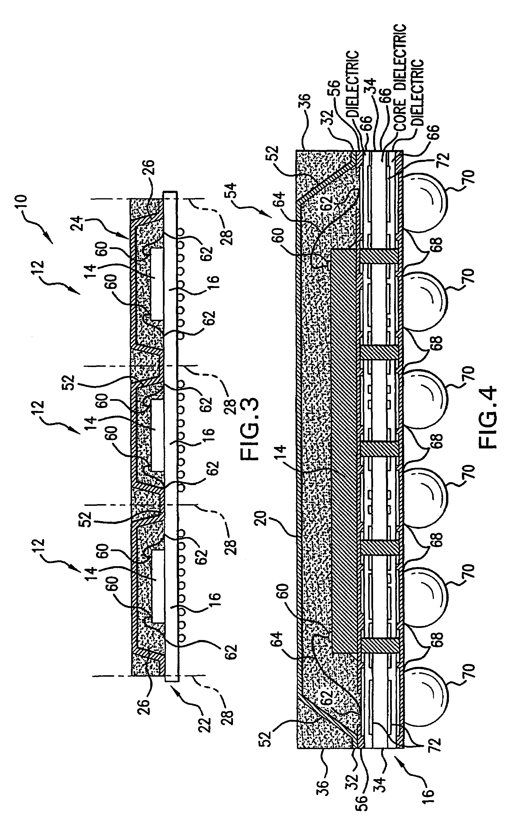
[0042]Referring to FIG. 1, a cross-sectional elevation view of a package strip, shown generally at 10, includes three interconnected package precursors 12, each of which includes a die 14 electrically connected to a substrate 16 and coated with a molding compound 18. Disposed above the die 14 and partially encapsulated in the molding compound 18 of each package precursor 12 is a heat spreader 20. The substrates 16 are interconnected to form part of a substrate strip 22, and the heat spreaders 20 are interconnected to form part of a heat spreader precursor 24. The heat spreader precursor 24 includes down-set leg portions 26 that are coupled to edges of the substrate strip 22.

[0043]In the manufacture of package strip 10, the heat spreader precursor 24 is placed over the dies 14 after the dies 14 have been electrically connected to the substrate strip 22 and before the molding compound 18 is applied to the heat spreader precursor 24, the dies 14, and a portion of the substrate strip 22...


PUM


Abstract

A heat spreader (20) is added to a package to enhance thermal and advantageously electrical performance. In manufacture, a heat spreader precursor (24) is advantageously placed over a group of dies and secured after bonding (e.g., wire or tape bonding or flip-chip bonding) and before matrix / block mold. For example, a package strip (10) may consist of a row (linear array) of groups of die attach areas (e.g. in a rectangular array of four). The heat spreader precursor (20) may accommodate one such group or multiple groups along the package strip (10). The package strip (10) may then be singulated to form the individual packages. Each singulated package includes a die (14), its associated substrate 16 (e.g., either a lead frame or interposer type substrate) and a portion of the heat spreader precursor (24) as a heat spreader (20).

Description

CROSS REFERENCE TO RELATED APPLICATION[0001]This application is a 371 of PCT / US03 / 29569 filed Sep. 23, 2003 which claims the benefit of U.S. Provisional Patent Application No. 60 / 415,189 filed on Sep. 30, 2002, which is incorporated by reference herein in its entirety.BACKGROUND OF THE INVENTION[0002]1. Field of the Invention[0003]This invention relates to semiconductor device packages. More particularly, this invention relates to thermally enhanced, molded plastic semiconductor device packages.[0004]2. Description of the Related Art[0005]Molded plastic packages provide environmental protection to integrated circuit devices (dies). Such packages typically include at least one semiconductor device (die) having its input / output (I / O) pads electrically connected to a lead frame type substrate or an interposer type substrate, with a molding compound coating the die and at least a portion of the substrate. Typically, the I / O pads on the die are electrically connected to bond sites on the...

Claims


Application Information

Patent Timeline
Patent Type & Authority Patents(United States)
IPC IPC(8): H01L23/495H01L23/31H01L23/433
CPCH01L21/561H01L23/3128H01L24/97H01L23/4334H01L2924/07802H01L2224/73265H01L2224/32225H01L2924/01006H01L2924/01005H01L24/48H01L2924/3025H01L2924/16152H01L2924/15311H01L2924/14H01L2924/01082H01L2924/01079H01L2924/01033H01L2924/01029H01L2924/01015H01L2924/01013H01L2224/97H01L2224/48247H01L2224/48227H01L2224/48091H01L2224/16245H01L23/49548H01L2224/85H01L2924/00014H01L2924/00H01L2224/73253H01L2224/81H01L2224/05599H01L2224/45099H01L2224/85399H01L2924/181H01L2924/00012H01L2224/45015H01L2924/207H01L23/28H01L23/36
Inventor LAU, DANIEL K.LAW, EDWARD L. T.
Owner ADVANCED INTERCONNECT TECH LTD
Why Eureka
Try Eureka