Circuit arrangement

a circuit and circuit technology, applied in the field of circuit arrangement, can solve problems such as controlling the charge amoun

Inactive Publication Date: 2007-08-21
SIGNIFY HLDG BV
View PDF8 Cites 8 Cited by
  • Summary
  • Abstract
  • Description
  • Claims
  • Application Information

AI Technical Summary

Benefits of technology

[0016]It has been found that a satisfactory control of the amplitude of the ignition voltage can be achieved by controlling only the amount of charge transported through only one of the switching elements. It is thus possible but unnecessary to control the amount of charge transported through each of the switches.
[0021]It has been found that the implementation of the first signal generator in this referred embodiment allows a comparatively easy and dependable generation of the first signal. It is possible to choose the second reference signal so that the voltage difference between the first and second input terminal of the integrator equals the voltage across the impedance. Alternatively a very simple embodiment of the first signal generator can be realized in case the third signal generator comprises a diode and a second capacitive element and the integrator comprises an ohmic resistor and the second capacitive element. Good results have been obtained in case the integrator comprises a transductance amplifier, equipped with two input terminals and an output terminal, for generating an output current proportional to the voltage difference between its input terminals and comprises a second capacitive element coupled to the output terminal of the transductance amplifier. The transductance amplifier can be formed in an integrated circuit in a simple and dependable way making use of two current mirrors and an ohmic resistor.

Problems solved by technology

It is thus possible but unnecessary to control the amount of charge transported through each of the switches.

Method used


Image

  • Circuit arrangement
  • Circuit arrangement
  • Circuit arrangement

Examples


Embodiment Construction

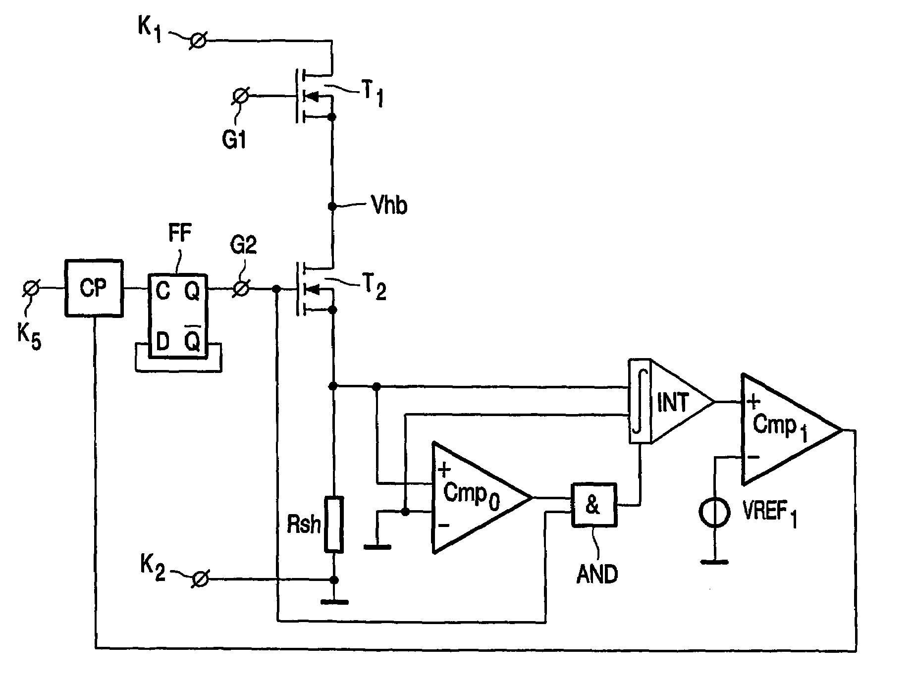
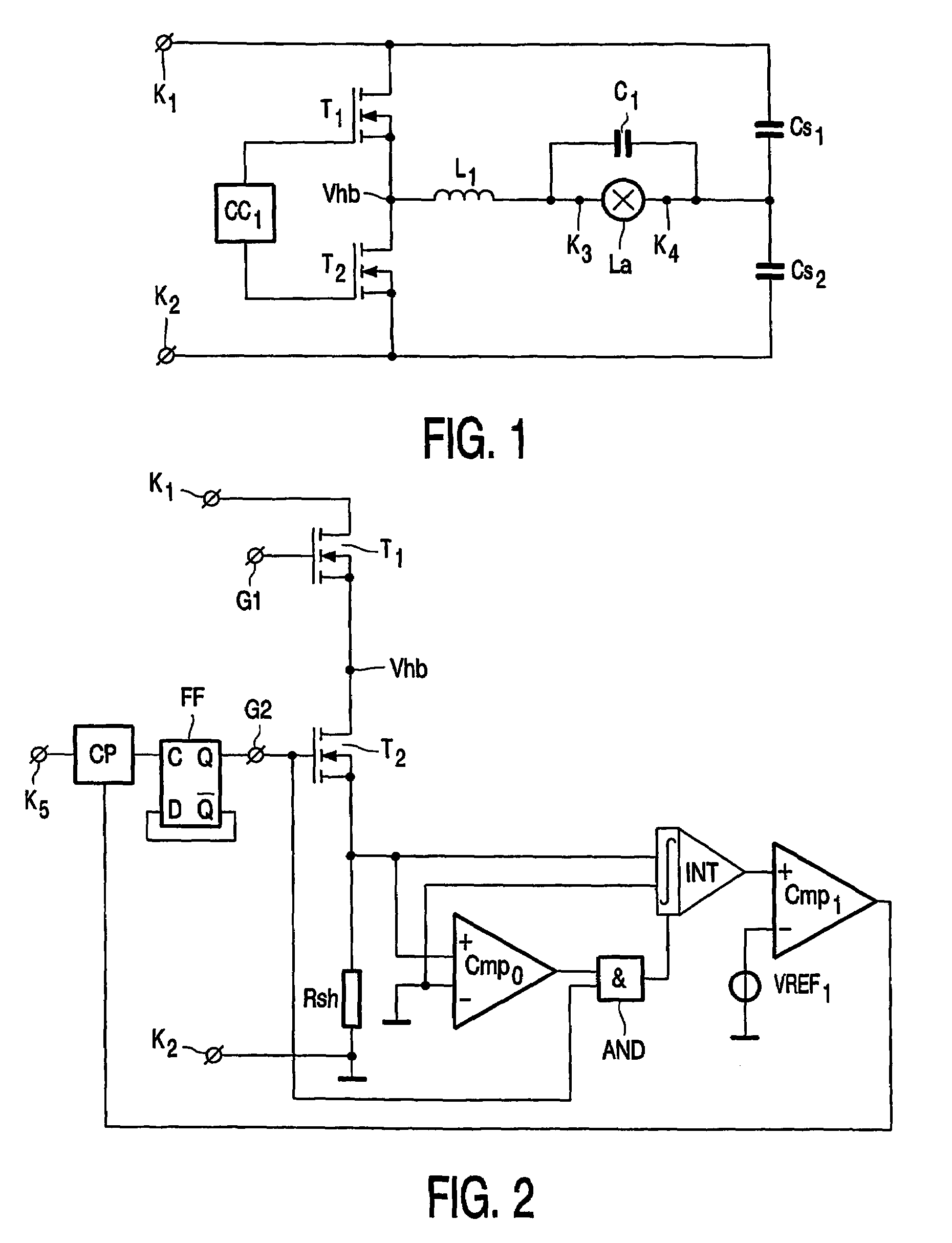
[0027]In FIG. 1, K1 and K2 are input terminals for connection to a supply voltage source. Input terminals K1 and K2 are connected by means of a series arrangement of a first switching element T1 and a second switching element T2. Circuit part CC1 is a control circuit for generating a periodic control signal for alternately rendering the first switching element T1 and the second switching element T2 conductive and non-conductive. Respective output terminals of circuit part CC1 are thereto coupled with respective control electrodes of the first and second switching element. Second switching element T2 is shunted by a series arrangement of an inductive element L1, a first capacitive element C1 and a capacitive element Cs2. A lamp La is connected in parallel to the first capacitive element C1 by means of lamp connection terminals K3 and K4. Inductive element L1, first capacitive element C1, capacitive element Cs2, lamp connection terminals K3 and K4 and the lamp La together form a load ...


PUM


Abstract

In a bride circuit comprising a lamp choke that might partially saturate during the ignition of the lamp, at least one of the switches is switched off when the amount of charge displaced through it in forward direction equals a predetermined value. Despite the partial paturation of the lamp choke the amplitude of the ignition voltage is thereby effectively controlled.

Description

[0001]This application is a 371 of PCT / 1B04 / 50021 field Jan. 14, 2004.BACKGROUND OF THE INVENTION[0002]The invention relates to a circuit arrangement for igniting and operating a lamp comprising[0003]input terminals for connection to a supply voltage source,[0004]a DC-AC-converter coupled to the input terminals and equipped with[0005]a series arrangement comprising a first and a second switching element and connecting the input terminals,[0006]a control circuit, coupled to respective control electrodes of the first switching element and the second switching element, for generating a periodic control signal for alternately rendering the first switching element and the second switching element conductive and non-conductive,[0007]a load circuit shunting one of the switching elements and comprising a series arrangement of an inductive element and a first capacitive element.[0008]Such a circuit arrangement is in common use, more in particular for the operation of fluorescent lamps. Gener...

Claims


Application Information

Patent Timeline
Patent Type & Authority Patents(United States)
IPC IPC(8): G05F1/00H05B41/282H05B41/392
CPCH05B41/2828Y10S315/07Y10S315/05
Inventor VELDMAN, PAUL ROBERTVAN DIJK, BERNHARD CHRISTIAANYU, JIANJUN
Owner SIGNIFY HLDG BV
Why Eureka
Try Eureka