Eureka AIR delivers breakthrough ideas for toughest innovation challenges, trusted by R&D personnel around the world.

Plasma-spraying device

a technology of plasma and spherical tube, which is applied in the direction of arc welding apparatus, electrical apparatus, coatings, etc., can solve the problems of low power consumption and low operating curren

Inactive Publication Date: 2007-11-06
PLASMA SURGICAL INC
View PDF6 Cites 7 Cited by
  • Summary
  • Abstract
  • Description
  • Claims
  • Application Information

AI Technical Summary

Benefits of technology

[0015]The object of the present invention is to provide an improved plasma-spraying device for low-power spraying of powdered materials, which allows satisfactory control of the coating properties as well as good homogeneity. Moreover, the invention shall allow spraying of coatings of materials and compounds with different properties. Finally, it shall also be possible to use the invention for breaking down powdered materials.

Problems solved by technology

Furthermore, the plasma-spraying device according to the invention allows the use of a plasma channel with a relatively small diameter, which results in a low power consumption and low operating currents.

Method used


Image

  • Plasma-spraying device
  • Plasma-spraying device
  • Plasma-spraying device

Examples


Embodiment Construction

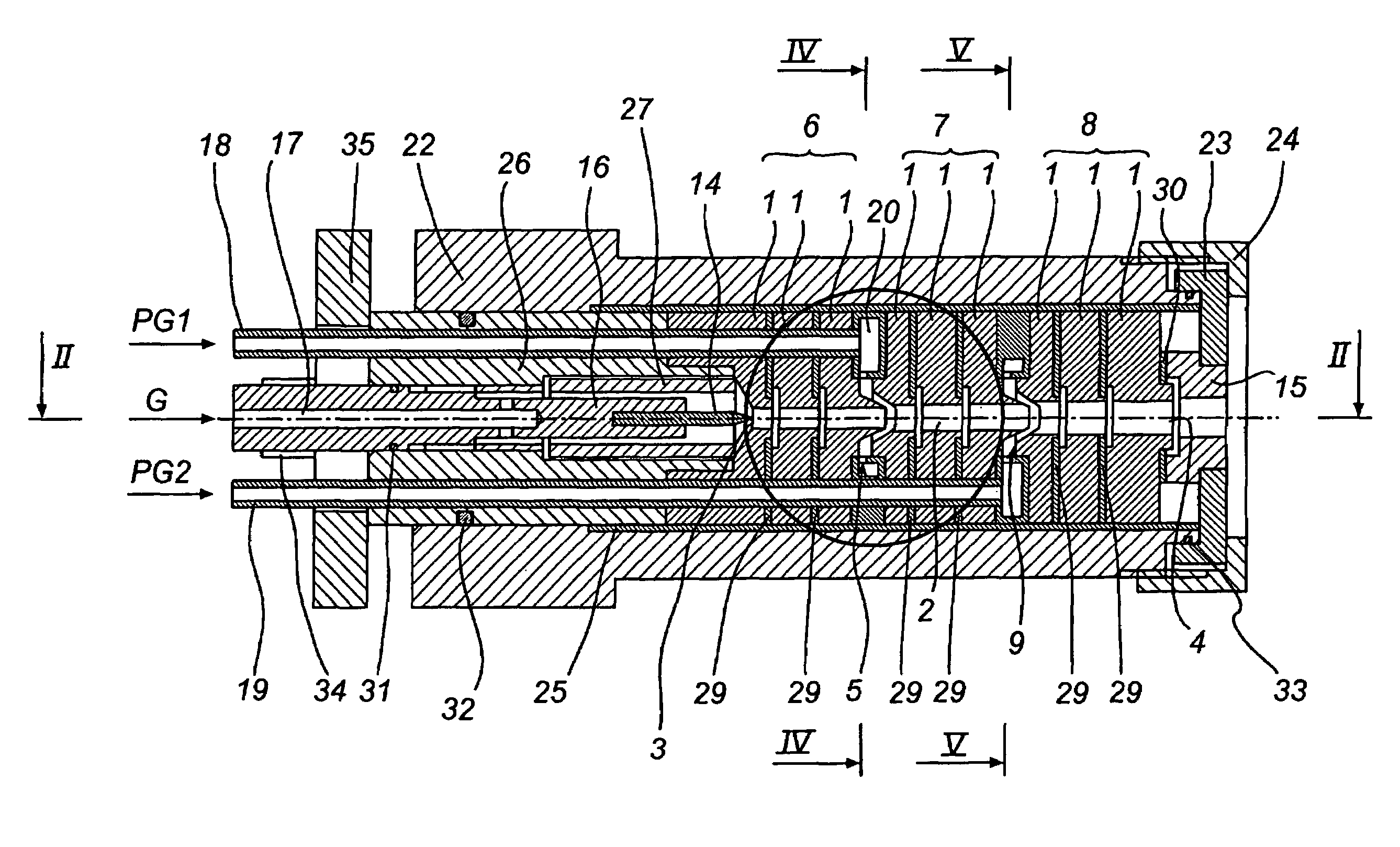
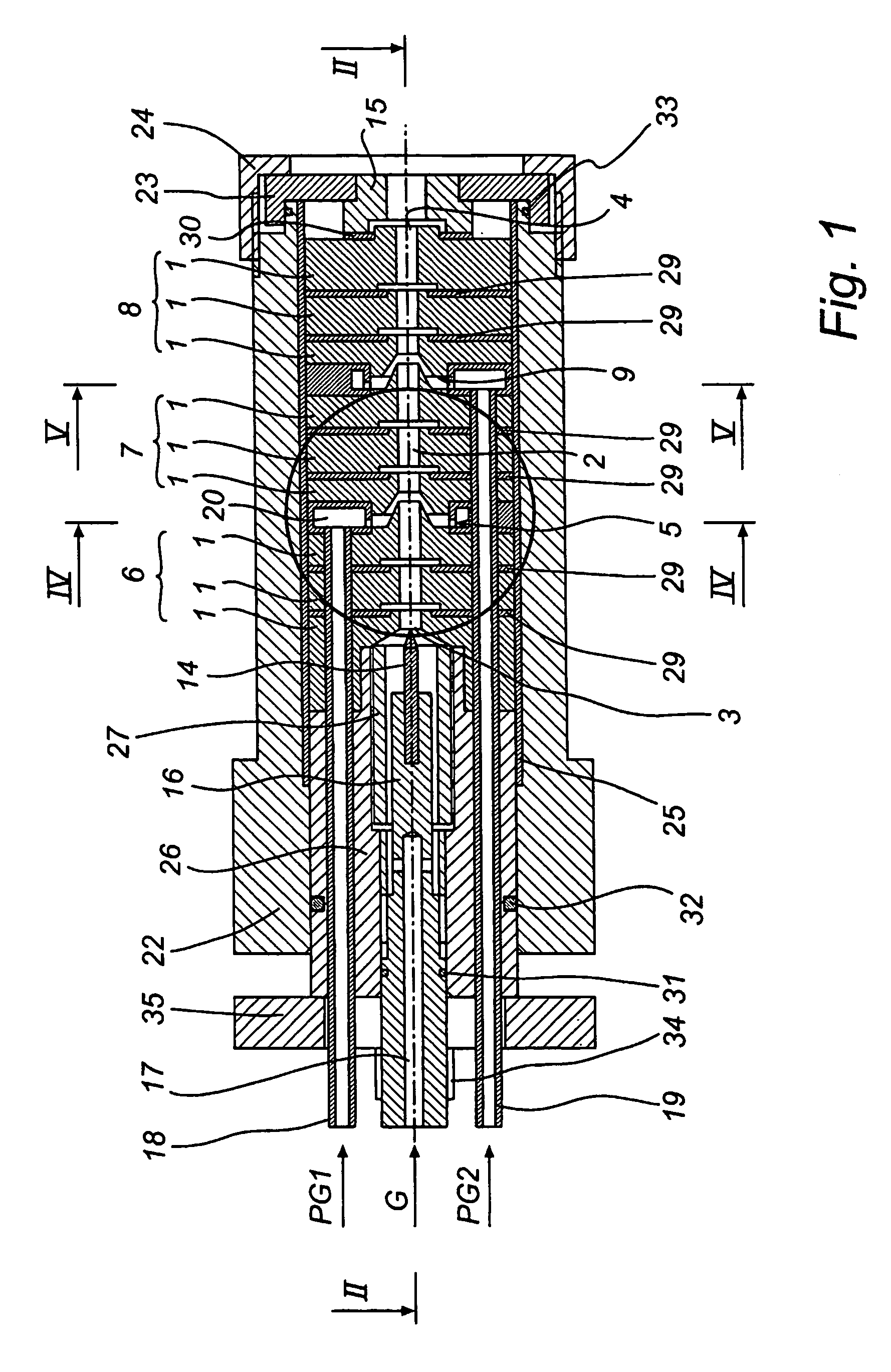
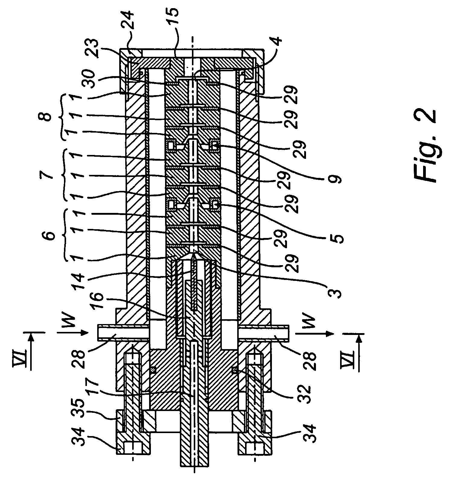
[0050]FIG. 1 illustrates one embodiment of a plasma-spraying device according to the invention comprising a cathode 14, preferably made of tungsten containing lanthanum, which is arranged in a cathode holder 16. The cathode holder 16 has an internal channel 17 which acts as a means for supplying plasma-generating gas G and as a cooler for the cathode holder 16. The device further comprises a number of coaxially arranged annular electrodes 1, which form a plasma channel 2. The plasma channel 2 extends from the cathode 14 at its inlet end 3 to an anode 15 at its outlet end 4. In use, an electric arc is generated in the device between the cathode 14 and the anode 15, which arc heats the plasma-generating gas to form a plasma. The internal channel 17 of the cathode holder thus opens into the inlet end 3 of the plasma channel, from where plasma will flow through the channel to the outlet end 4 of the plasma channel located adjacent the anode 15, where it is discharged.

[0051]A first means...


PUM

PropertyMeasurementUnit
angleaaaaaaaaaa
angleaaaaaaaaaa
angleaaaaaaaaaa

Abstract

Example embodiments relate to a plasma-spraying device for spraying a powdered material, including electrodes, which may form a plasma channel having an inlet end and an outlet end, and a unit for supplying the powdered material to the plasma channel. The powder supply unit may be arranged between a first section of the electrodes located upstream of the powder supply unit and a second section of the electrodes located downstream of the powder supply, as seen in the direction of plasma flow of the plasma channel.

Description

FIELD OF THE INVENTION[0001]The present invention relates to a plasma-spraying device for spraying a powdered material, comprising electrodes, which form a plasma channel having an inlet end and an outlet end, and a means for supplying said powdered material to said plasma channel. The invention further concerns a method of plasma-spraying. Finally, the invention also concerns the use of a plasma-spraying device for incinerating a powdered material.BACKGROUND ART[0002]Plasma-spraying devices or plasmatrons are used for low-power thermal spraying of powdered materials, for example in connection with different kinds of surface-coating. Such devices generally comprise a cathode, an anode and a plasma channel formed therebetween. During use of the device an electric arc is generated in the plasma channel, between the anode and the cathode, and gas is then introduced in the plasma channel for forming a plasma. The plasma jet thus flows through the plasma channel from an inlet end adjacen...

Claims


Application Information

Patent Timeline
Patent Type & Authority Patents(United States)
IPC IPC(8): B23K9/00H05H1/32C23C4/00C23C4/12H05H1/34H05H1/42
CPCH05H1/42H05H2001/3452H05H1/3452
Inventor SUSLOV, NIKOLAY
Owner PLASMA SURGICAL INC
Why Eureka
Eureka Blog
Learn More