Method for motion vector estimation

a technology of motion vector estimation and motion vector, which is applied in the field of apparatus and method for motion vector estimation of coding video, can solve the problems of limited motion estimation process for encoding image frames, and achieve the effects of reducing processing results, reducing power consumption, and substantially reducing processing overhead for encoding video

Active Publication Date: 2007-08-21
TEXAS INSTR INC
View PDF4 Cites 131 Cited by
  • Summary
  • Abstract
  • Description
  • Claims
  • Application Information

AI Technical Summary

Benefits of technology

[0011]Embodiments in accordance with the first and second aspects of the invention may advantageously determine whether or not a current block and a neighbor block are motion correlated. Thus, the process of motion estimation for encoding the image frames may be limited to a simple first stage relying on the correlation with neighboring blocks if the current block and neighbor block are motion correlated. The check for correlation is done with reference to a previous image frame. Otherwise, a more extensive process for motion estimation may be undertaken. Thus, the processing overhead for encoding the video can be substantially reduced for circumstances in which it is determined that the current block and enable block are motion correlated, with a more complex process used when such motion correlation is not determined. This is particularly advantageous for real time coding, and also for mobile or portable platforms utilizing such coding since reduced processing results in reduced power consumption.

Problems solved by technology

Thus, the process of motion estimation for encoding the image frames may be limited to a simple first stage relying on the correlation with neighboring blocks if the current block and neighbor block are motion correlated.

Method used


Image

  • Method for motion vector estimation
  • Method for motion vector estimation
  • Method for motion vector estimation

Examples


Embodiment Construction

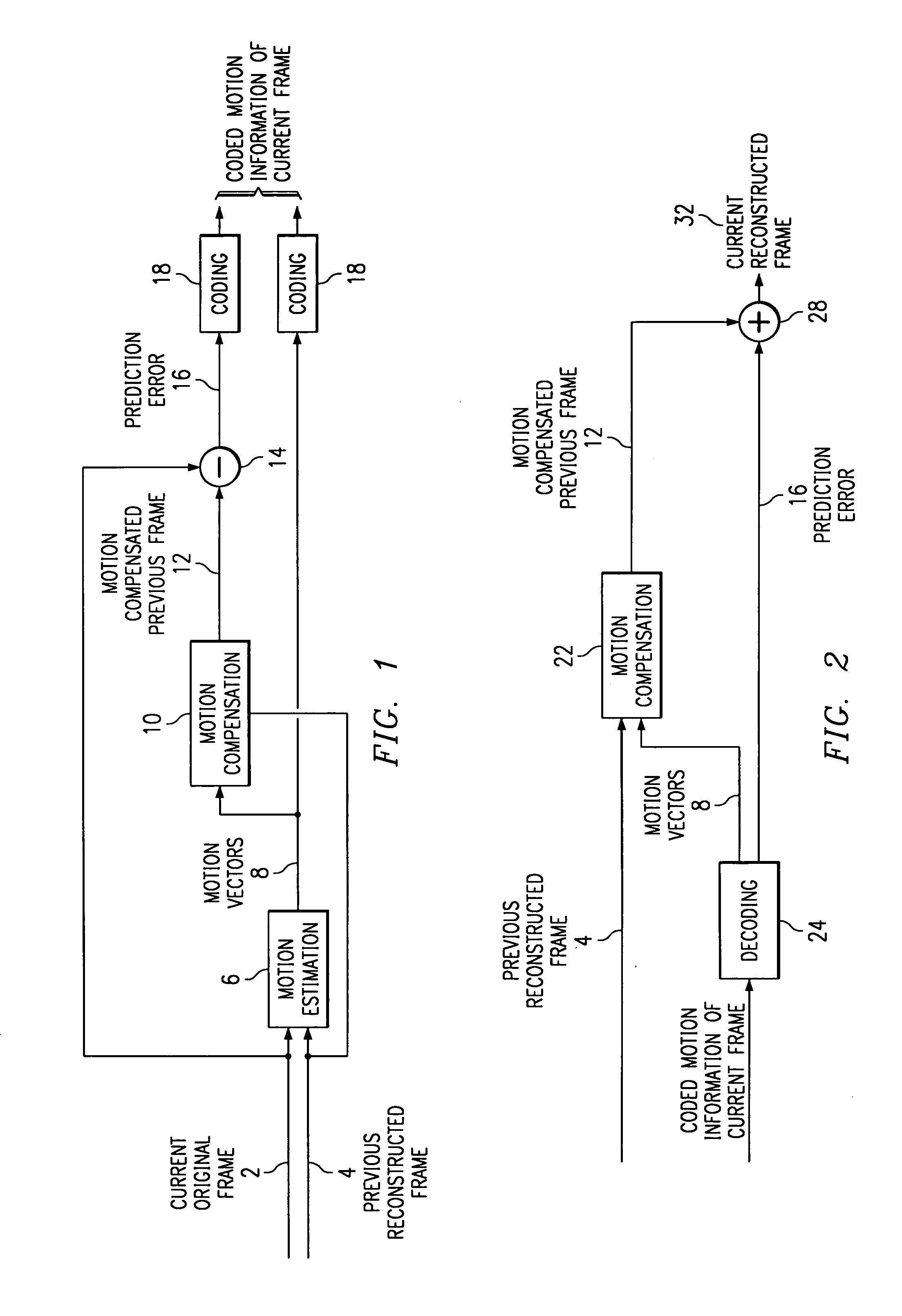
[0044]The basic principle of motion compensated video coding will now be described with reference to FIGS. 1 and 2. FIG. 1 illustrates a block diagram of motion compensated encoding circuitry. FIG. 2 illustrates a block diagram of motion compensated decoding circuitry. First, motion between the previous frame 4 and the current frame 2 is estimated in a motion estimator 6 and described through motion vectors 8. Depending on the coding scheme, motion vectors may describe the motion of individual pixels or a group (block) of pixels of a frame. Using these motion vectors, the image content of the previous frame 4 is then transformed towards the estimated new position in the current frame in motion compensation block 10 in accordance with the motion vectors 8, to form a motion compensated previous frame 12. The motion between two frames can rarely be compensated perfectly. Therefore, the motion compensated previous frame 12 is subtracted from the current original frame 2 in comparator 14...


PUM


Abstract

A method and apparatus for encoding video includes selecting a prediction motion vector for a current block of a current image frame from respective motion vectors of two or more neighbor blocks of the current block. Then the current block and a neighbor block corresponding to said prediction motion vector are checked to determine whether they are motion correlated. Checking motion correlation includes determining that the difference between the best correlation from the correlation of the current block with one or more neighbor blocks and the correlation of the neighbor block with a block in the previous image frame at a location defined by the prediction motion vector fulfils a predetermined criterion.

Description

[0001]This application claims priority from European Patent Application No. 01402335.2 filed Sep. 10, 2001.TECHNICAL FIELD OF THE INVENTION[0002]The present invention relates to an apparatus and method for motion vector estimation for coding video. In particular, to motion compensated video coding.BACKGROUND OF THE INVENTION[0003]In video coding, an original image is converted into a digital format by sampling in space and time, and by quantizing in brightness or color. The digitally formatted image comprises a sequence of image frames. Each image frame has an array of pixels, each pixel having a value corresponding to the brightness or color of the image at the point represented by the pixel. A sequence of such image frames provides a video image.[0004]For a typical image frame comprising 1024×1024 pixels, each pixel having a value between 0 and 255, results in an image frame comprising 1 megabyte of data per image. For typical television systems, 25 images per second are displayed...

Claims


Application Information

Patent Timeline
Patent Type & Authority Patents(United States)
IPC IPC(8): H04N7/12G06T7/20H04N7/26
CPCG06T7/202H04N19/533H04N19/56G06T2207/10016G06T7/231
Inventor SOHM, OLIVER P.
Owner TEXAS INSTR INC
Why Eureka
Try Eureka