Shield arrangement for ECG lead wires

Inactive Publication Date: 2007-08-21
GE HEALTHCARE FINLAND
View PDF12 Cites 5 Cited by
  • Summary
  • Abstract
  • Description
  • Claims
  • Application Information

AI Technical Summary

Benefits of technology

[0020]In one embodiment of the invention the grounding circuit consists of one or more passive components, like simple resistors, or resistors and capacitors to further tailor the frequency response of the circuit. The

Problems solved by technology

In case one or multiple precordial electrodes are added to the monitoring setup, this kind o

Method used


Image

  • Shield arrangement for ECG lead wires
  • Shield arrangement for ECG lead wires
  • Shield arrangement for ECG lead wires

Examples


Embodiment Construction

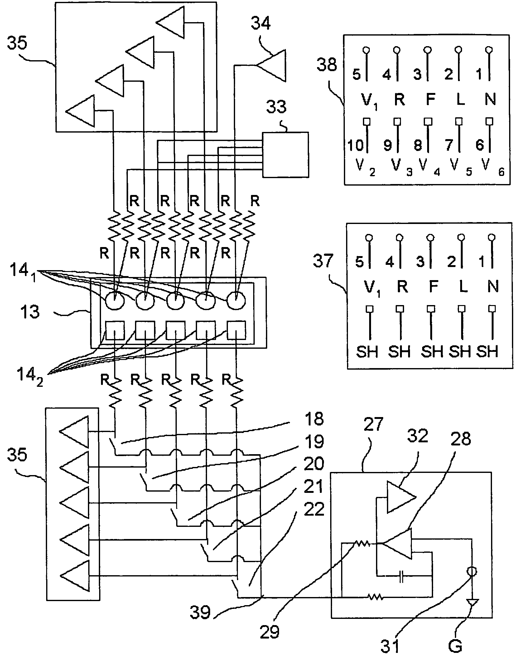
[0026]Reference will now be made in detail to the embodiments of the present invention. FIG. 4 represents a complete system in which a shield grounding circuit 27 according to the invention is applied to prior art system.

[0027]As shown in FIG. 4, the collecting connector 13 in the prior art embodiment contains a number of connector elements 14; 141, 142 corresponding to the number of measuring electrodes defined in the 12-lead ECG standard, i.e. a total of 10 connector elements. As can be seen, the connection elements for the lead wires 1-4 connected to the limb electrodes R, F, L, N and for one lead wire 5 of the precordial electrode V1 are arranged in the upper first row 141 in the collecting connector 13. The connection elements for the rest of the lead wires 6-10 connected to the rest of the precordial electrodes V2, V3, V4, V5, V6 are arranged in the lower second row 142 in the collecting connector 13 the second row 142 being in paired alignment with said first row.

[0028]The el...


PUM


Abstract

A grounding arrangement in a system using the same connector for 5- and 12-lead connection in ECG-measurement. If 5-lead configuration is used, the connector elements of the 12-lead connection are used for grounding of lead wire shields through a current limiting circuit exhibiting non-linear voltage-current characteristics.

Description

CROSS REFERENCE TO RELATED APPLICATION[0001]The present application claims priority from European Patent Application No. 03396003.0, filed Jan. 9, 2003.FIELD OF THE INVENTION[0002]The present invention relates to a system for ECG monitoring. In particular, the present invention relates to a novel system and method for grounding of the shields of electrode lead wires.BACKGROUND TO THE INVENTION[0003]In prior art is known a system for ECG monitoring as represented by the diagram in FIG. 1. In FIG. 1, the same patient P is diagrammatically represented by two pictures of the torso, where the lower picture shows a standard four-point placement of measuring electrodes R, F, L and N (so-called limb electrodes). For the sake of clarity, the upper picture separately shows a standard placement of ECG measuring electrodes, i.e. precordial electrodes V1, V2, V3, V4, V5, V6 on the patient's thorax. Together the limb electrodes and precordial electrodes form a so-called 12-lead connection system....

Claims


Application Information

Patent Timeline
IPC IPC(8): A61B5/0428A61B5/308
CPCA61B5/0402Y10S128/908Y10S128/901A61B5/318A61B5/321
Inventor VIRTANEN, JUHA
Owner GE HEALTHCARE FINLAND
Why Eureka
Try Eureka