Data center system and method for controlling the same

a data center and data center technology, applied in the field of data center systems, can solve the problems of inadequate use of a system containing two different positioned storage systems, and achieve the effects of improving the degree of data redundancy and information processing system redundancy, reducing efficiency, and overall well-balanced performan

Inactive Publication Date: 2007-08-21
HITACHI LTD
View PDF27 Cites 26 Cited by
  • Summary
  • Abstract
  • Description
  • Claims
  • Application Information

AI Technical Summary

Benefits of technology

[0015]The use of the above configuration increases the degree of data redundancy and information processing system redundancy. Further, a synchronous data transfer is made between an active information processing system at a copy source and an information processing system near the copy source while an asynchronous data transfer is made between the active information processing system at the copy source and an information processing system far from the copy source. Therefore, the advantages brought by a synchronous data transfer and the advantages brought by an asynchronous data transfer can be both enjoyed on the whole. Performing a remote copy operation based on the synchronous transfer method provides an advantage in that both storage systems can retain the same data. However, if this method is used for a data transfer to a remotely positioned storage system, efficiency may decrease because a data copy operation takes a considerable amount of time. On the other hand, a remote copy operation based on the asynchronous transfer method produces a temporary data difference between connected storage systems. However, the remote copy process will not interrupt the processes of the storage systems or their higher-level computers.
[0016]As shown in FIG. 2, therefore, overall well-balanced performance is provided by the above configuration in which a remote copy operation based on the synchronous transfer method is performed between a storage system at a remote copy source and a storage system installed near the copy source and the asynchronous transfer method is used for a remote copy operation relative to a storage system that is installed far from the storage system at the remote copy source. In other words, when there are three data centers (copy source data center, near copy destination data center, and far copy destination data center), which each include an internal storage system and are interconnected via a network, high efficiency can be achieved by using the synchronous transfer method to perform a remote copy operation from the copy source data center to the near copy destination data center and the asynchronous transfer method to perform a remote copy operation from the copy source data center to the far copy destination data center. This type of configuration is very effective as a multi-point remote copy configuration containing three or more data centers.

Problems solved by technology

Therefore, the use of a system containing two differently positioned storage systems is now inadequate.

Method used


Image

  • Data center system and method for controlling the same
  • Data center system and method for controlling the same
  • Data center system and method for controlling the same

Examples


Embodiment Construction

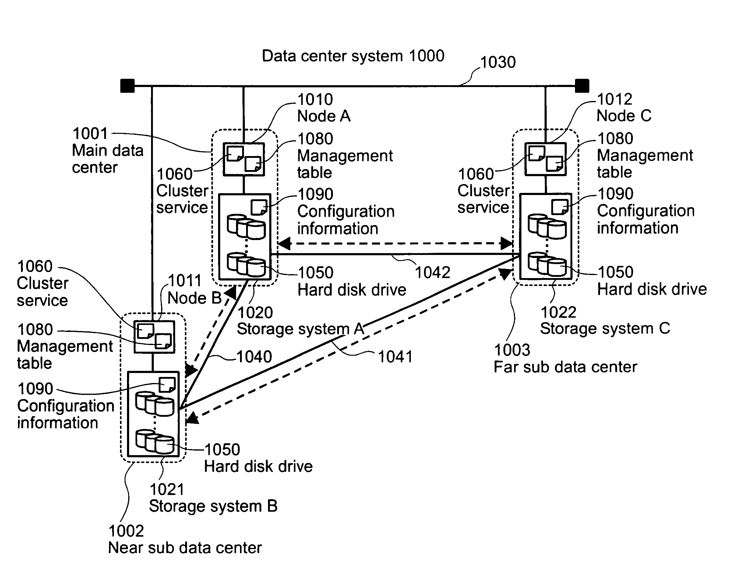
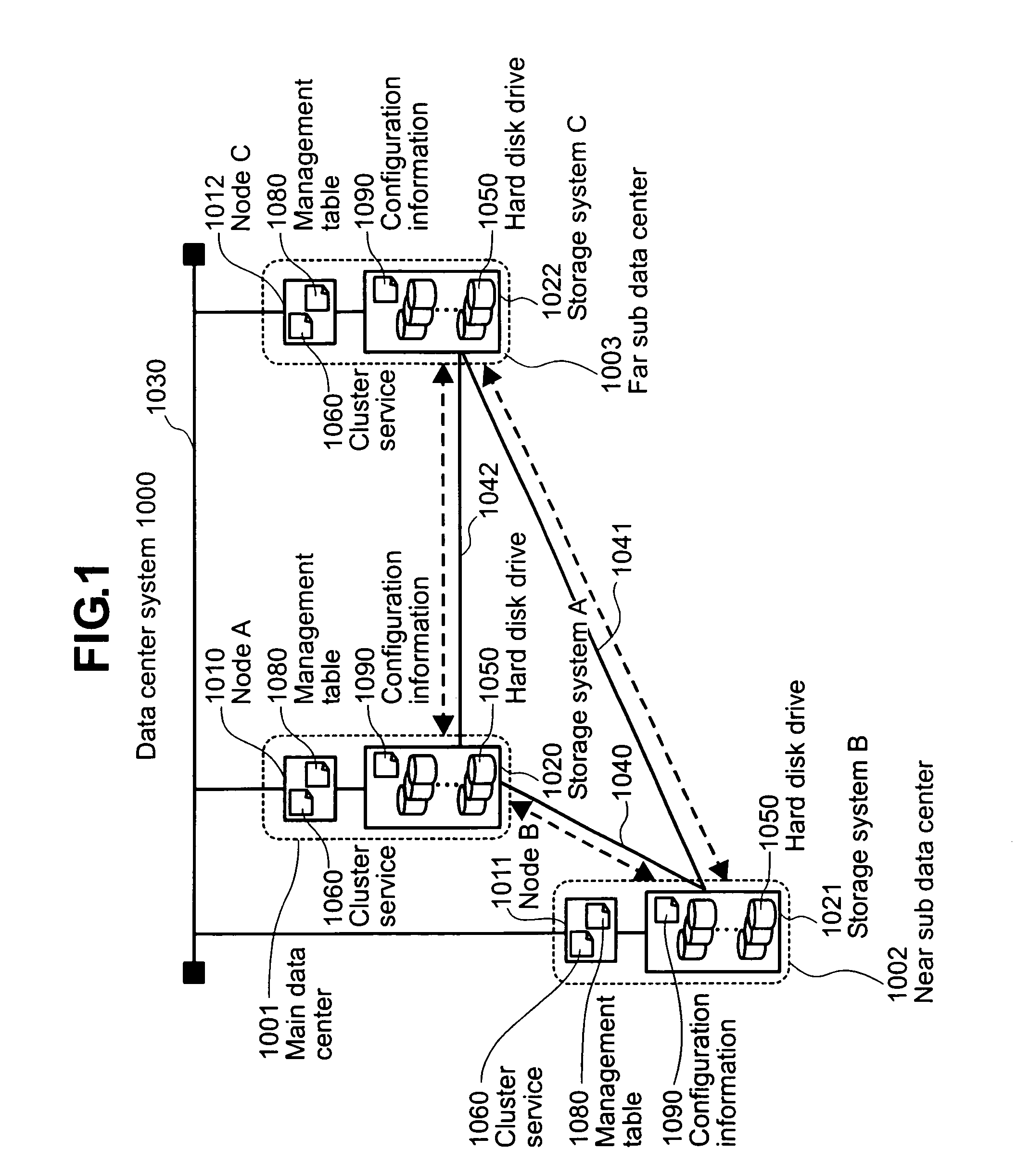
[0043]Specific embodiments of the present invention will now be described in detail with reference to the accompanying drawings. FIG. 1 shows an example of a data center system according to the present embodiment. The data center system 1000 comprises three data centers: a main data center 1001, a near sub data center 1002, and a far sub data center 1003, whose distance from the main data center is greater than the distance between the near sub data center and main data center.

[0044]The main data center 1001 comprises node A 1010 and storage system A 1020. In like manner, sub data centers 1002 and 1003 each comprise a node and a storage system connected to that node. Each node is a personal computer, workstation, or other device that may function as a host computer. Node 1010, node 1011, and node 1012 each have software 1060 for providing a cluster service and a management table 1080. These nodes are interconnected via a network 1030 such as a TCP / IP-based network. The data center s...


PUM


Abstract

In one aspect of the invention, A data center system comprises a plurality of data centers each including a computer and a storage system. The computers each include a memory area for storing information about an order of operating priorities among the computers and another memory area for storing a cluster service program, whereby when an active computer from the computers fails as a failed computer, the cluster service program is executed to select a standby computer from the remaining computers according to the information about the order of operating priorities to be a failover computer to take over processing from the failed computer. The information about the order of operating priorities may relate to the types of remote copy operation used between the storage systems.

Description

CROSS-REFERENCES TO RELATED APPLICATIONS[0001]This application relates to and claims priority from Japanese Patent Application No. 2003-183743, filed on Jun. 27, 2003, the entire disclosure of which is incorporated herein by reference.BACKGROUND OF THE INVENTION[0002]The present invention relates to a data center system comprising a plurality of data centers, and more particularly to failover / failback control that is exercised when host computers in a cluster configuration are connected to each data center.[0003]Computers have begun to retain valuable information as the society has been increasingly IT-driven in recent years. If, for instance, a natural calamity happens unexpectedly, it is extremely important that data be safety saved and retained. Under such a circumstance, it is essential to provide storage system / data redundancy and establish proper means for storage system / data recovery.[0004]Meanwhile, a cluster service can be used as a means for providing system redundancy. A ...

Claims


Application Information

Patent Timeline
Patent Type & Authority Patents(United States)
IPC IPC(8): G06F15/173G06F11/20G06F12/00G06F15/00H02H3/05
CPCG06F11/1482G06F11/2028G06F11/2071
Inventor SUGIURA, YOKOACHIWA, KYOSUKE
Owner HITACHI LTD
Why Eureka
Try Eureka