
Trace cache filtering

a cache block and filtering technology, applied in the field of cache memory devices, can solve the problems of increasing the number of traces built during execution, affecting the performance or power of the system, and affecting the assembly of instructions from multiple non-contiguous cache blocks

Inactive Publication Date: 2007-08-21
INTEL CORP
View PDF36 Cites 5 Cited by
  • Summary
  • Abstract
  • Description
  • Claims
  • Application Information

AI Technical Summary

Problems solved by technology

Therefore, fetching a large number of useful instructions per cycle requires accurate prediction of multiple branch targets and the assembly of instructions from multiple non-contiguous cache blocks is a more difficult task.
Techniques that aim to improve instruction bandwidth severely increase the number of traces built during the execution.
This causes degradation in the performance or power of the system since trace-cache consumes large power when active.

Method used


Image

  • Trace cache filtering
  • Trace cache filtering
  • Trace cache filtering

Examples


Embodiment Construction

[0012]In the following, for purposes of explanation, numerous details are set forth in order to provide a thorough understanding of the present invention. However, it will be apparent to one skilled in the art that theses specific details are not required in order to practice the present invention. In other instances, well-known electrical structures and circuits are shown in block diagram form in order not to obscure the present invention.

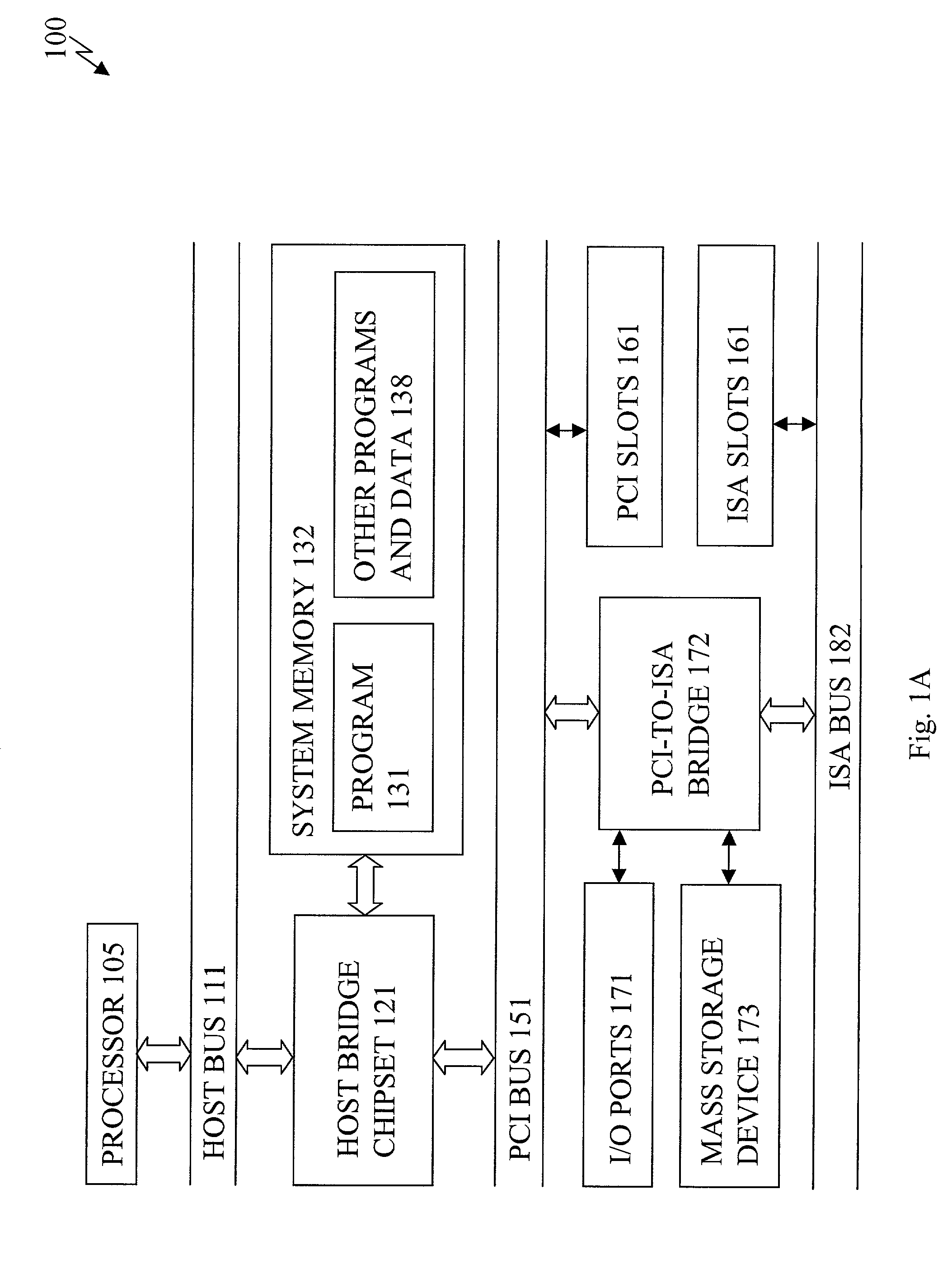
[0013]FIG. 1A is a diagram illustrating a computer system 100 in which one embodiment of the present invention can be practiced. The computer system 100 includes a processor 105, a host bus 111, a host bridge chipset 121, a system memory 132, a peripheral component interconnect (PCI) bus 151, PCI slots 161, a PCI-to-industry standard architecture (ISA) bridge 172, mass storage device 173, Input / Output (I / O) ports 171, an ISA bus 182, and ISA slots 181.

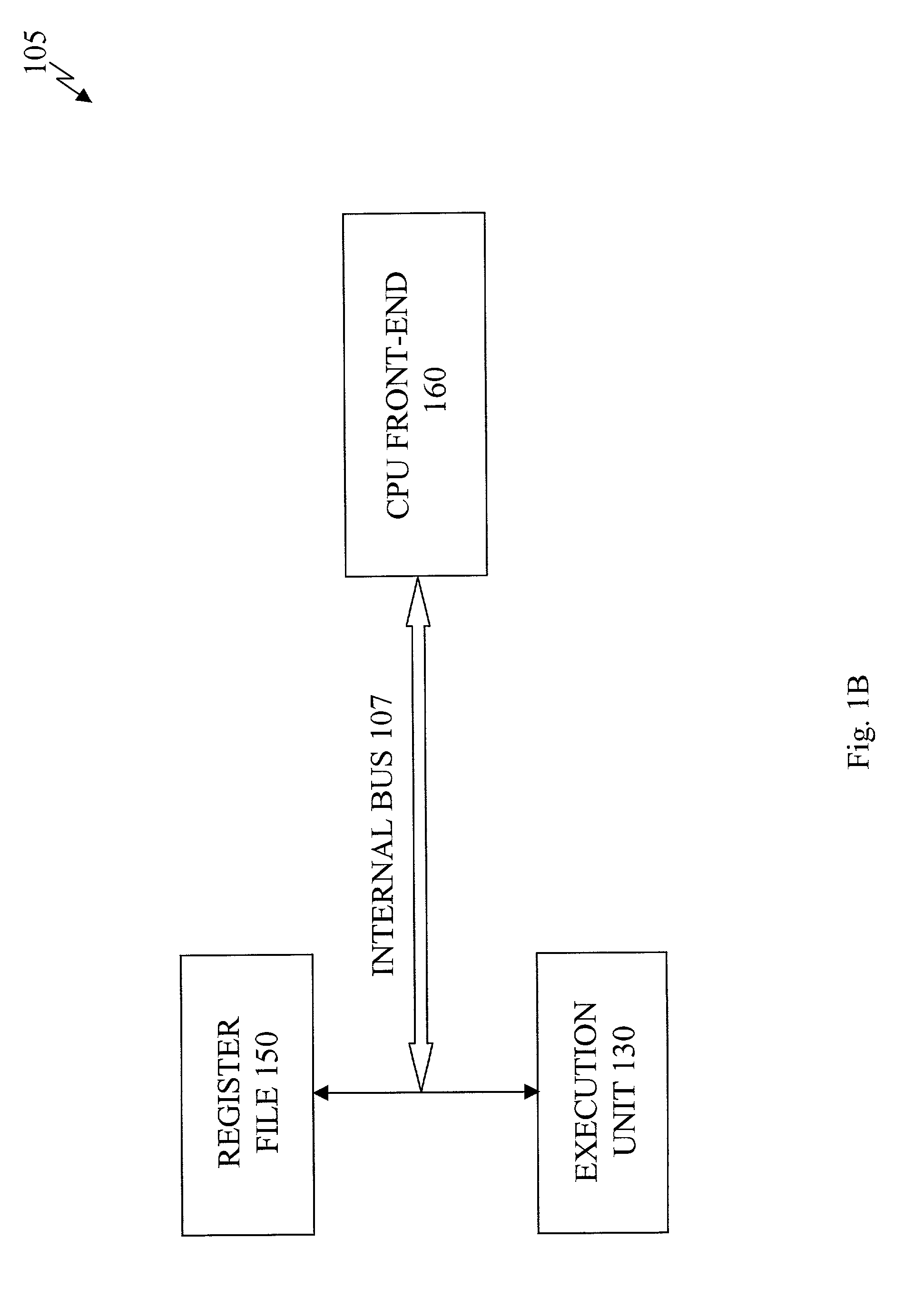
[0014]The processor 105 represents a central processing unit (CPU) of any type of architecture, s...


PUM


Abstract

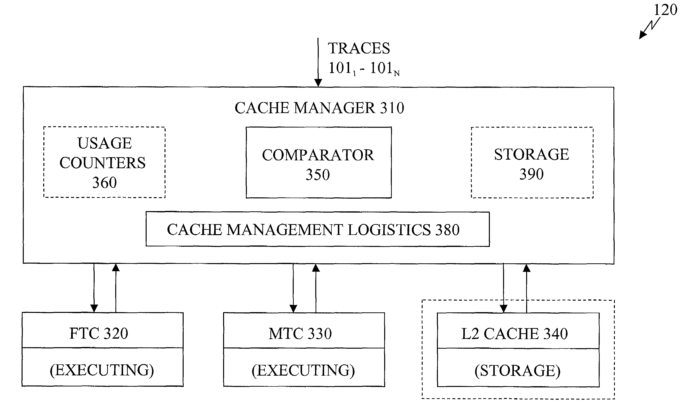
A cache management logistics controls a transfer of a trace. A first cache couples to the cache management logistics to evict the trace based on a replacement mechanism. A second cache couples to the cache management logistics to receive the trace based on a number of accesses to the trace.

Description

FIELD OF THE INVENTION[0001]This invention relates to memory devices. In particular, the invention relates to cache memory devices.BACKGROUND OF THE INVENTION[0002]Modern high-end processors require high throughput front-ends in order to cope with increasing performance demand. Fetching a large number of useful instructions (e.g., instructions residing on the correct path) per cycle is relatively easy task if those instructions are arranged sequentially. However, on an average every few instructions there is a branch instruction. Therefore, fetching a large number of useful instructions per cycle requires accurate prediction of multiple branch targets and the assembly of instructions from multiple non-contiguous cache blocks is a more difficult task.[0003]One way of increasing the effectiveness of conventional fetch is reducing the number of fetch discontinuities along the execution path of the program. Loop unrolling, code motion, and branch alignment are a few examples of compiler...

Claims


Application Information

Patent Timeline
IPC IPC(8): G06F13/00G06F12/00G06F9/38G06F12/08G06F12/12
CPCG06F9/3802G06F9/3808G06F12/0897G06F12/122Y02B60/1225G06F12/0875Y02D10/00
Inventor MENDELSON, ABRAHAMROSNER, RONIRONEN, RONNY
Owner INTEL CORP
Learn More