Oil strainer support structure in engine

a support structure and engine technology, applied in the field of engine, can solve the problems of increased restricted layout, increased number of parts, etc., and achieve the effect of preventing an increase in the number of parts and avoiding an increase in the weight and size of the engin

Active Publication Date: 2007-08-28
HONDA MOTOR CO LTD
View PDF3 Cites 25 Cited by
  • Summary
  • Abstract
  • Description
  • Claims
  • Application Information

AI Technical Summary

Benefits of technology

[0005]The present invention has been accomplished in view of the above-mentioned circumstances. One embodiment of the present invention provides an oil strainer support structure in an engine which not only can avoid an increase in the weight and the size of an engine and prevent an increase in the number of parts but also can strongly support an oil strainer.
[0010]According to an embodiment of the present invention, since a plurality of vertically long plate-like strainer support portions are integrally formed on a side face of the casing lower portion and are abutted against and supported by the bottom of the oil pan, the strength of the casing lower portion can be enhanced by allowing each strainer support portion to fulfill the function of a reinforcing rib. In addition, the support strength of the oil strainer can be enhanced while making it unnecessary to specially enhance the support strength on the crank case side which supports the upper end portion of the oil strainer. Thus, it is possible to strongly support the oil strainer while avoiding an increase in the size and the weight of the engine and an increase in the number of parts. Moreover, since each strainer support portion also fulfills the function of a partition wall which restricts the movement of oil within the oil pan, it is unnecessary to dispose any other partition wall than the oil strainer within the oil pan, whereby it is also possible to decrease the number of parts.
[0011]According to an embodiment of the present invention, since each strainer support portion is formed so as to include a larger projection from the casing toward the lower side, the flow of oil can be made uniform effectively in the vicinity of the suction port and it is possible to keep the suction resistance of oil low into the suction port for improving the suction efficiency.
[0012]According to an embodiment of the present invention, the movement of oil within the oil pan caused by a sudden acceleration or deceleration of the vehicle or caused by movement in the transverse direction of the vehicle can be restricted effectively by the strainer support portions.
[0013]According to an embodiment of the present invention, longitudinal movements of oil between the right and left side walls of the generally V-shaped oil pan having a narrow lower portion and the oil strainer caused by a sudden acceleration or deceleration of the motorcycle can be prevented effectively by the strainer support portions which are disposed at least partially between both the right and left sides of the casing and both the right and left sides of the oil pan.

Problems solved by technology

However, such structures result in an increase in the weight and the size of the engine.
More particularly, in the case where the oil strainer is supported by a stay, not only an increase in the number of parts results, but also the layout is restricted for example by a partition wall disposed within the oil pan.

Method used


Image

  • Oil strainer support structure in engine
  • Oil strainer support structure in engine
  • Oil strainer support structure in engine

Examples


first embodiment

[0031]FIGS. 1 to 12 illustrate the present invention.

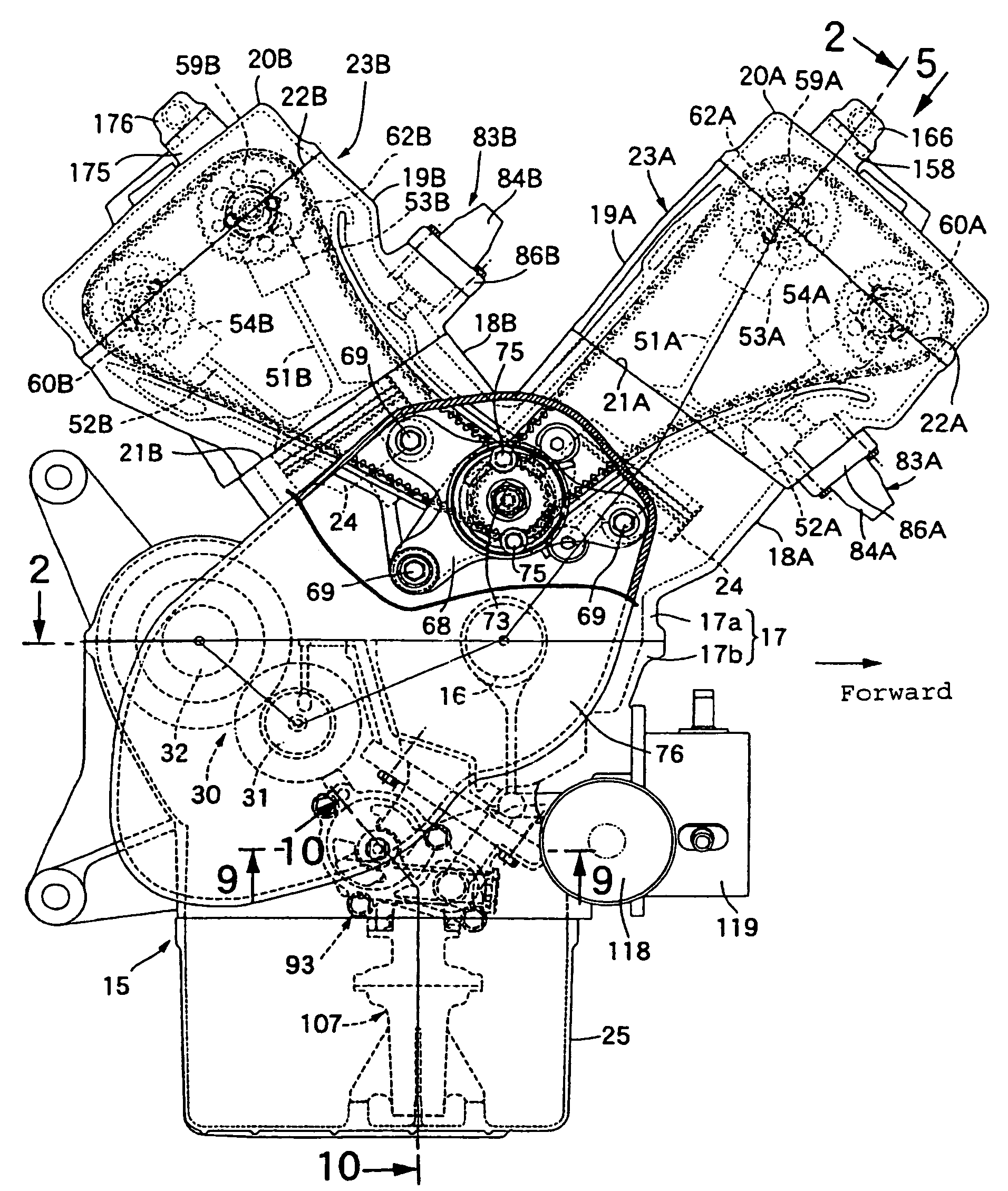
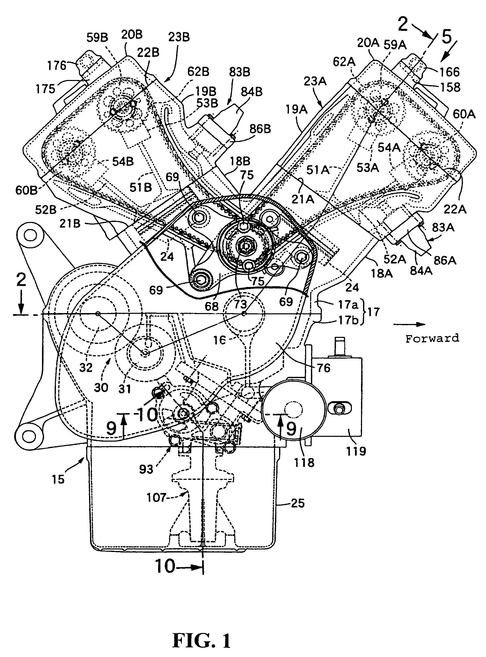
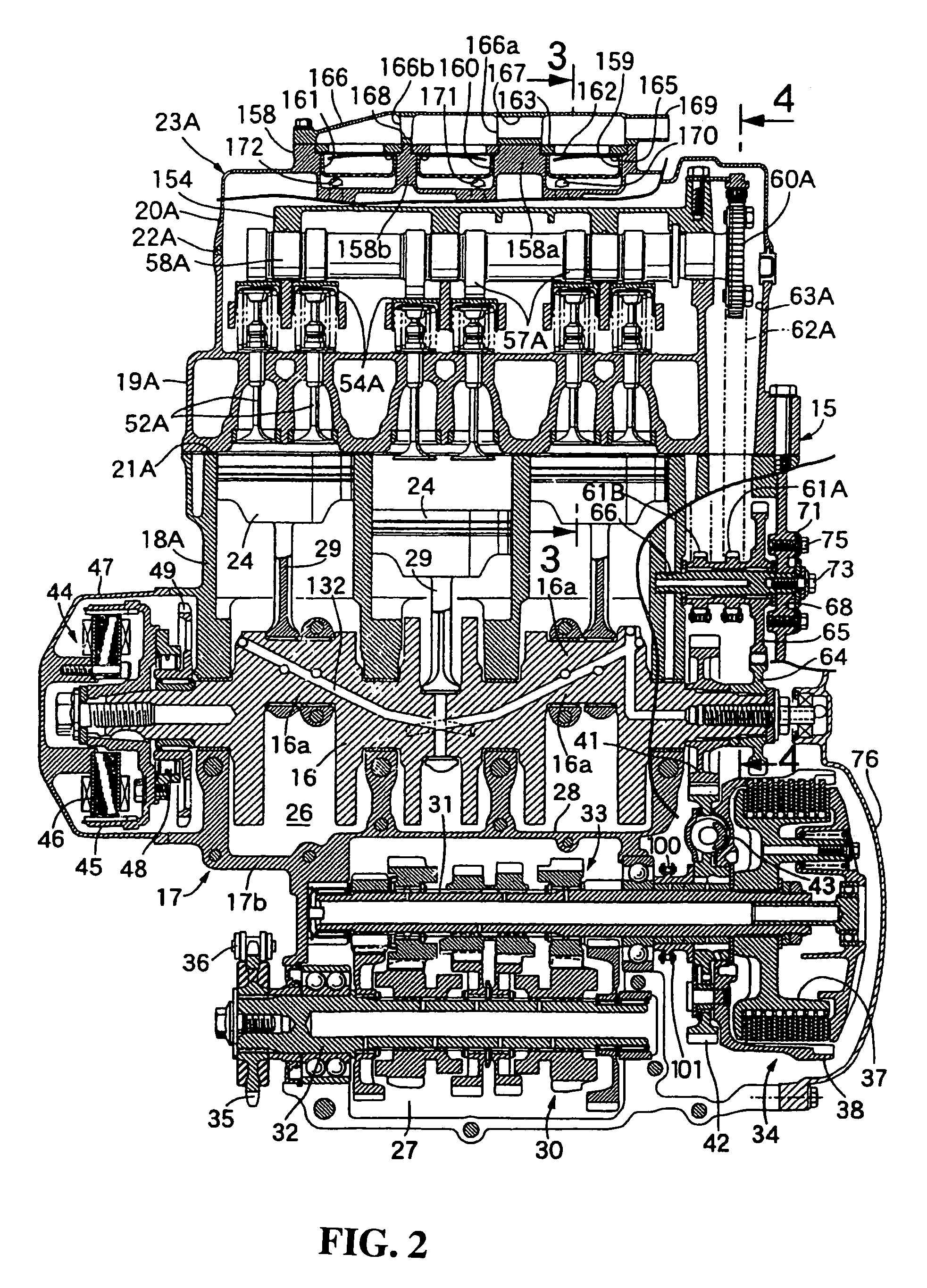
[0032]Referring first to FIG. 1, a V-type engine of, say, five cylinder is mounted on a vehicle, e.g., a motorcycle. An engine body 15 of the engine includes a crank case 17 which rotatably supports a crank shaft 16 having an axis extending in the transverse direction of the motorcycle. A first cylinder block 18A is joined to the crank case 17 on a front side in a motorcycle advancing direction with a first cylinder head 19A being joined to an upper-end joining surface 21A of the first cylinder block 18A and a first head cover 20A being joined to an upper-end joining surface 22A of the first cylinder head 19A. A second cylinder block 18B is joined to the crank case 17 on a rear side in the motorcycle advancing direction with a second cylinder head 19B being joined to an upper-end joining surface 21B of the second cylinder block 18B, and a second head cover 20B being joined to an upper-end joining surface 22B of the second cylinder...

second embodiment

[0109]In addition, the strainer support portions 112′ are formed integrally with the casing 108′ so as to be positioned at least partially between both the right and left sides of the casing 108′ and both the right and left sides of the oil pan 25′ when looking in the motorcycle advancing direction. In this second embodiment, the strainer support portions 112′ are integrally formed at equal intervals in the circumferential direction on the side face of the casing 108′ so as to intersect the motorcycle advancing direction at an angle of 30° for example. The strainer support portions 112′ provided in a pair on each of the right and left sides are formed integrally on the side face of the casing 108′ so as to be partially positioned between both the right and left sides of the casing 108′ and both the right and left sides of the oil pan 25′. The crossing angle of the strainer support portions 112′ relative to the motorcycle advancing direction may be set arbitrarily, for example at 45°...


PUM


Abstract

In an engine wherein an upper end portion of a casing of an oil strainer disposed within an oil pan is supported on a crank case side and a suction port is formed in a lower end of the casing whose lower portion is formed in a funnel shape, the oil strainer is supported firmly while preventing an increase in weight and size of the engine and an increase in the number of parts. A plurality of vertically long plate-like strainer support portions are integrally formed on a lower side face of a casing of an oil strainer for abutting against and for being supported by the bottom of an oil pan.

Description

CROSS-REFERENCE TO RELATED APPLICATIONS[0001]The present application claims priority under 35 USC 119 to Japanese Patent Application No. 2004-376323 filed on Dec. 27, 2004 the entire contents of which are hereby incorporated by reference.FIELD OF THE INVENTION[0002]The present invention relates to an engine wherein an oil pan for the storage of oil to be fed to various portions of an engine body is joined to a lower portion of a crank case provided in the engine body. An upper end portion of a casing of an oil strainer disposed within the oil pan is supported on the crank case side. A suction port is formed in a lower end of the casing whose lower portion is formed in the shape of a funnel. More particularly, the present invention is concerned with an improvement of an oil strainer support structure.DESCRIPTION OF BACKGROUND ART[0003]Japanese Utility Model Laid-Open No. Hei 3-54219 discloses an engine wherein an oil strainer includes a casing whose lower portion is formed in a funne...

Claims


Application Information

Patent Timeline
Patent Type & Authority Patents(United States)
IPC IPC(8): F01M1/02
CPCF01M11/0004F01M2011/007
Inventor GUNJI, TORUSUGIURA, HIROYUKI
Owner HONDA MOTOR CO LTD
Why Eureka
Try Eureka