Deployable video arm

a video arm and support technology, applied in the field of support arms, can solve the problem of extremely limited space and achieve the effect of reducing the required spa

Active Publication Date: 2007-08-28
SATTERFIELD JOHNNY A
View PDF13 Cites 61 Cited by
  • Summary
  • Abstract
  • Description
  • Claims
  • Application Information

AI Technical Summary

Benefits of technology

[0006]The present invention is a video arm that supports and deploys a video display monitor, such as a flat panel monitor, of the type typically found on passenger aircraft, trains, cars and other vehicles. In these environments, space is extremely limited, thereby requiring a compact, easy to use system to deploy the monitors. The present invention is designed to reduce the required space by employing a unique and simple deployment mechanism to move the monitor between a stowed position and a deployed position. The deployment mechanism allows the support to be at least partially deployed from the stowed position without pivoting the support.
[0009]The video monitor support includes a means for preventing travel of the shaft in a first direction between the stowed and deployed positions as well as a way of selectively disengaging that preventing means. In one embodiment of the present invention, travel of the shaft in the first direction is prevented via a latch that engages the carriage. Likewise, one way of selectively disengaging the preventing means involves a button operatively connected to the latch for pivoting the latch to disengage from the carriage. The disengagement of the latch from the carriage allows the shaft to move between the stowed and deployed positions.
[0012]In an embodiment of the present invention, the shaft is disposed within a housing having an open end in the stowed position. The shaft extends through the open end of the housing in the deployed position. The rail is connected to a side of the housing and operatively engages the carriage. A constant force spring connected to the housing near an end of the rail is operatively connected to the carriage for pulling the carriage along the rail, moving the shaft between the stowed and deployed positions. A brake controls the speed of the carriage along the rail as the shaft travels between the stowed and deployed positions.

Problems solved by technology

In these environments, space is extremely limited, thereby requiring a compact, easy to use system to deploy the monitors.

Method used


Image

  • Deployable video arm
  • Deployable video arm
  • Deployable video arm

Examples


Embodiment Construction

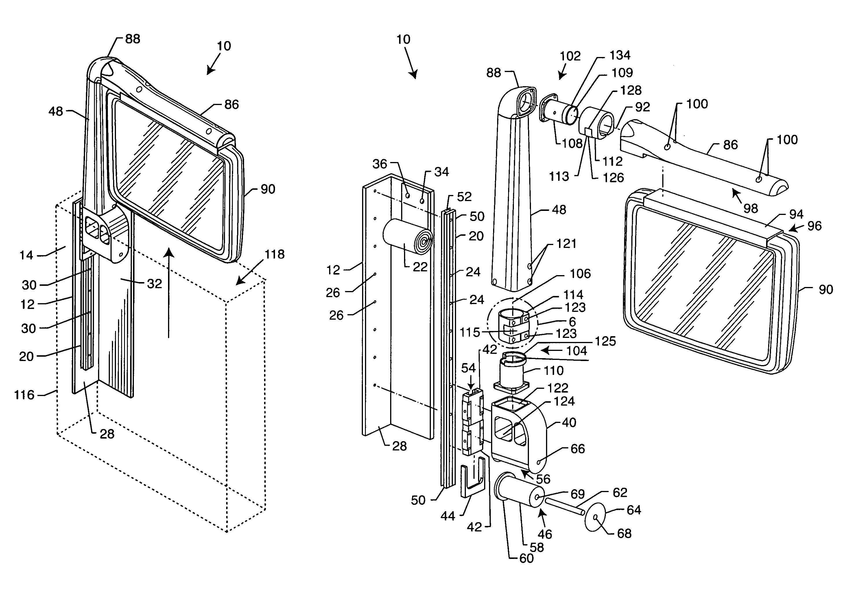
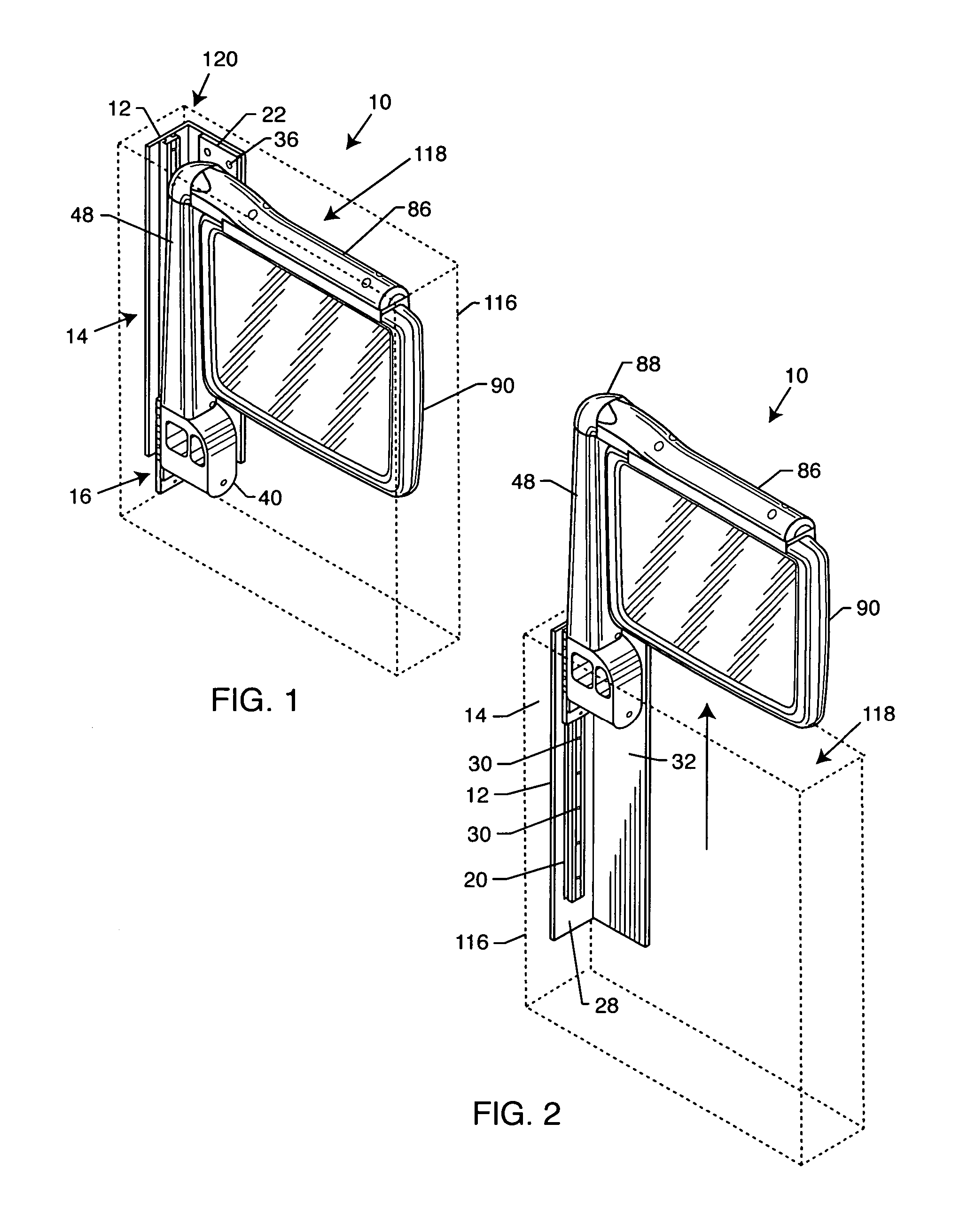
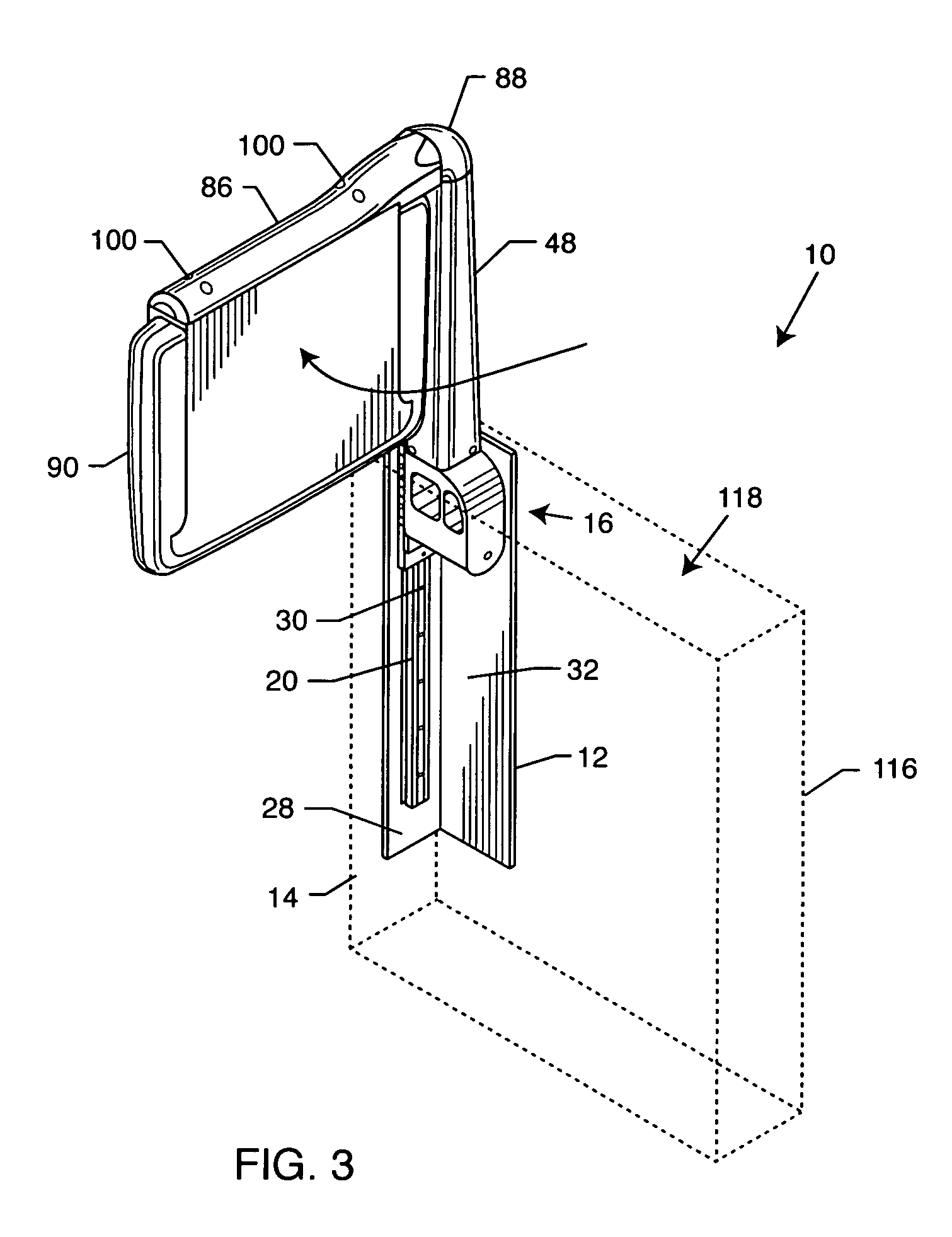
[0022]As shown in FIGS. 1-7 for purposes of illustration, the present invention resides in a video monitor support 10 movable between stowed and deployed positions. The support 10 includes a support structure or base 12 which acts as the main structural support for the entire video monitor support 10. The base 12 may come in various forms including, without limitation, an L-shaped bracket or the like.

[0023]The base 12 is attachable to a surface 14 and a carriage assembly 16 is fixed to the base 12. The surface 14 may be a surface on a vehicle (e.g., aircraft) bulkhead, an exterior side of a vehicle chair (not shown) or a side of a console housing or compartment located next to or part of the vehicle passenger chair.

[0024]The base 12 holds a rail 20 and one end of a laminated, rolled, constant force spring 22. The spring 22 may come in various forms including, but not limited to, two thin constant force springs placed one on top of the other and then coiled up together. Aligned apert...


PUM


Abstract

A video monitor support movable between stowed and deployed positions includes a base attachable to a surface and a carriage fixed to the base. The carriage includes a shaft extendible between the stowed and deployed positions. A constant linear force is applied to the shaft between the stowed and deployed positions, and a mount is fixed to the shaft opposite the carriage for supporting a video monitor.

Description

BACKGROUND OF THE INVENTION[0001]The present invention relates generally to support arms. More particularly, the present invention relates to a video monitor support arm.[0002]With each passing year, commercial airline companies are continuously striving to provide improved services for their customers as well as improving passenger comfort and convenience. On many airlines, it is standard for each passenger to have their own personal video display monitor associated with their chair or seat to provide the passenger with in-flight entertainment and / or information. As a matter of safety and convenience, the screen must be easily stored and retracted.[0003]Many different types of supports have been proposed to provide a video display monitor that can be stowed when not in use. However, such supports have their limitations. For example, U.S. Pat. No. 5,000,511 discloses an apparatus for attaching a display monitor to a seat. However, this apparatus relies on the use of pivoting mechani...

Claims


Application Information

Patent Timeline
Patent Type & Authority Patents(United States)
IPC IPC(8): E04G3/00
CPCB60R11/0235B64D11/0015B64D11/06B60R2011/0082B60R2011/0087B64D11/00153H04N5/64A47C7/386
Inventor SATTERFIELD, JOHNNY A.
Owner SATTERFIELD JOHNNY A
Why Eureka
Try Eureka