Photocatalyst deodorizer

a photocatalyst and deodorizer technology, applied in the direction of physical/chemical process catalysts, heating types, separation processes, etc., can solve the problems of reducing the light intensity of the photocatalyst, and affecting the effect of deodorizing filter

Inactive Publication Date: 2004-09-02
ZEXEL VALEO CLIMATE CONTROL CORP SAITAMA
View PDF2 Cites 43 Cited by
  • Summary
  • Abstract
  • Description
  • Claims
  • Application Information

AI Technical Summary

Problems solved by technology

However, in the technology of this same publication, because a space is required for arranging the cylindrical lamp on a side portion of the deodorizing filter, the apparatus becomes large.
Further, the airflow can be easily bypassed (short-circuited) between the deodorizing filter and the cylindrical lamp, and this lowers the dust collecting effect.
However, even though on the one hand it is believed that folding a filter in a pleated shape will extend the dust collecting filter life and improve the dust collecting efficiency, it is difficult to shine the light that activates the photocatalyst on the total surface of a deodorizing filter in which peaks and valleys are formed due to the pleats.
Accordingly, there are places in the deodorizing filter that do not receive light irradiation and can not carry out sufficient catalytic action, and this lowers the deodorizing efficiency.
Further, when a deodorizing filter is folded in a pleated shape, the thickness of the filter is increased, and because

Method used


Image

  • Photocatalyst deodorizer
  • Photocatalyst deodorizer
  • Photocatalyst deodorizer

Examples


first embodiment

[0052] First Embodiment

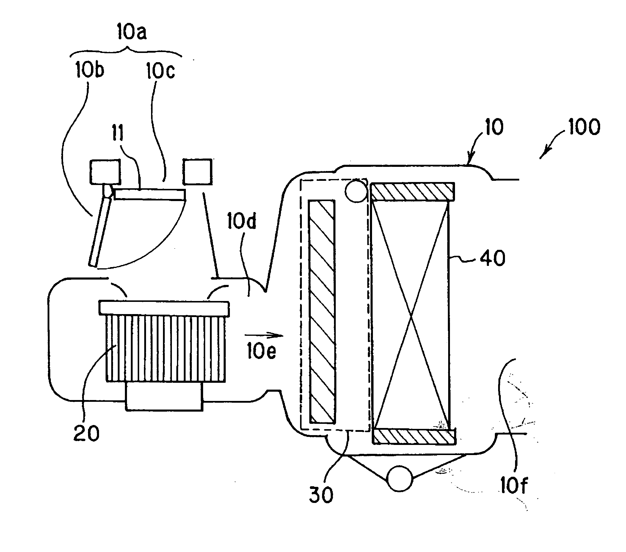
[0053] FIG. 1 shows a side schematic view when a photocatalyst deodorizer according to the present invention is installed inside an air conditioner for a vehicle. This photocatalyst deodorizer 100 is equipped with an air conditioner body 10. An air intake port 10a formed from an inside air intake port 10b and an outside air intake port 10c which are opened and closed by a damper 11, an air passage 10d connected to the air intake port 10a, and a purified air discharge port 10f are formed in the air conditioner body 10. A blower 20, a filter unit 30 and an evaporator 40 are provided in that order from the upstream side in the air passage 10d. When the blower 20 is driven, air is sucked inside the air passage 10d from the open side of the air intake port 10a. This air forms an airflow 10e which passes through the filter unit 30 and is cooled by the evaporator 40. Then, the airflow 10e passes through an air mixing door (not shown in the drawings), a heater (not sh...

second embodiment

[0080] Second Embodiment

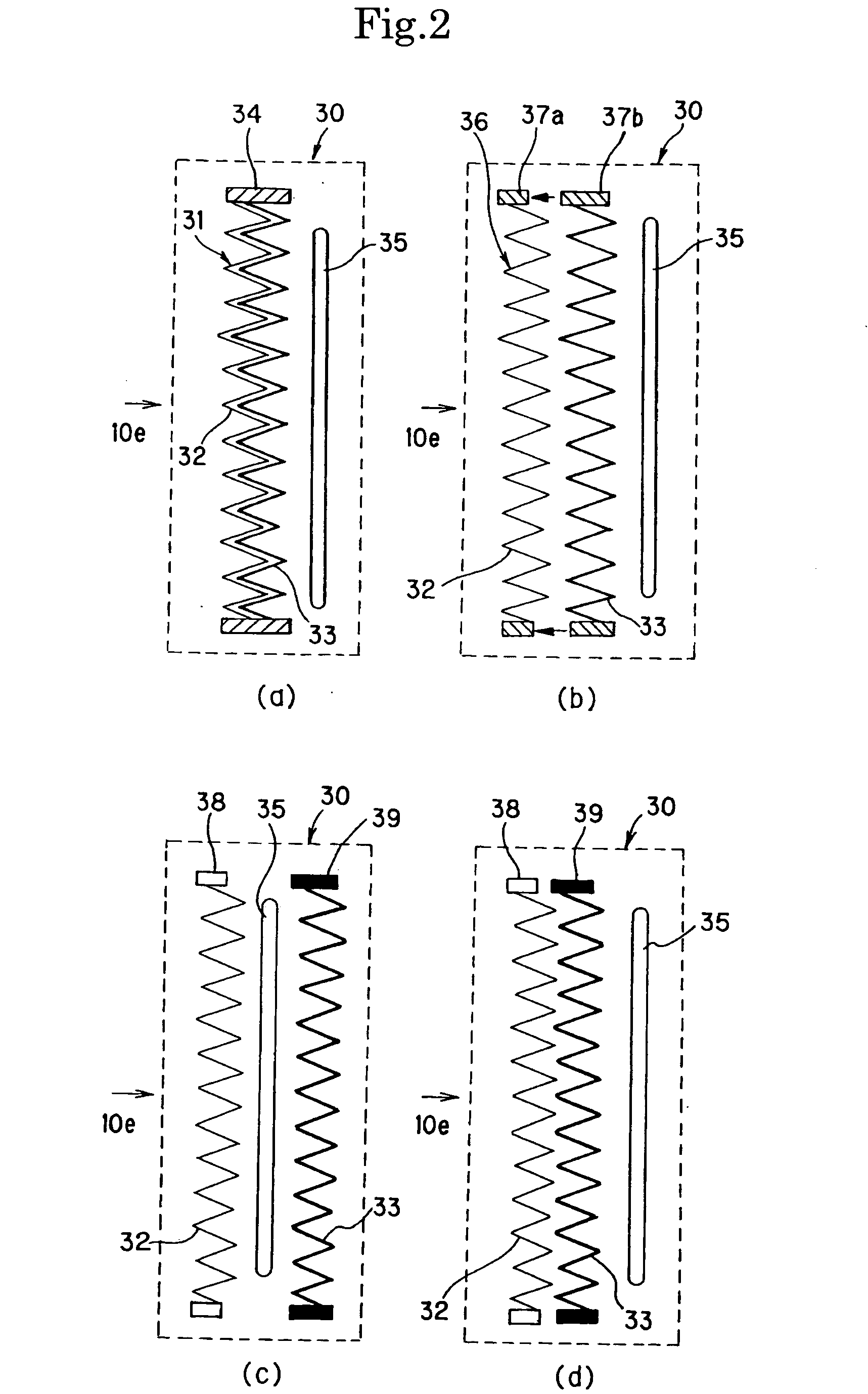
[0081] FIG. 6 shows side schematic views when a photocatalyst deodorizer according to the present invention is installed inside an air conditioner for a vehicle, wherein (a) shows the case where there is one tubular light source, and (b) shows the case where there are two tubular light sources. Except for the filter unit 30, the structure is the same as FIG. 1.

[0082] The filter unit 30 is an air purifying portion which is described in detail below using FIGS. 7.about.13, and is constructed from a dust collecting filter processed to have a pleated shape, a deodorizing filter processed to have a pleated shape and carrying a photocatalyst, and a tubular light source which emits light that activates the photocatalyst, wherein a depression capable of housing the tubular light source is provided in the deodorizing filter in a direction which intersects the peaks and valleys of the pleats, and the tubular light source is arranged inside the depression to obtain tota...

third embodiment

[0109] Third Embodiment

[0110] A description will be given for the case where light-emitting diode elements are used as a light source for activating the photocatalyst. With reference to FIGS. 14.about.18, a description will be given for a photocatalyst deodorizer 200 according to the present invention. FIG. 14 shows a schematic view when the photocatalyst deodorizer 200 according to the present invention is installed inside an air conditioner for a vehicle. The basic structure is the same as FIG. 1, but the difference is that a light source 80 in which light-emitting diode elements are arranged is used in place of the tubular light source in the filter unit 30.

[0111] The filter unit 30 is an air purifying portion, and is constructed in the same way as in the first embodiment from a dust collecting filter processed to have a pleated shape, a deodorizing filter processed to have a pleated shape and carrying a photocatalyst, and a light source which emits light that activates the photo...


PUM

PropertyMeasurementUnit
Lengthaaaaaaaaaa
Timeaaaaaaaaaa
Volumeaaaaaaaaaa

Abstract

Object of this invention is to provide a photocatalyst deodorizer wherein it is possible to extend the life and increasing an efficiency of filters, and it is possible to activate a photocatalyst which a deodorizing filter carries, by optimizing the positional relation between a tubular light source for emitting light to activatee a photocatalyst and a deodorizing filter, and an emission angle of the tubular light source. Further a photocatalyst deodorizer of this invention makes it easy to maintenance and replacement of filters and the tubular light source. A photocatalyst deodorizer comprising an air purifying portion which is removably arranged in an air passage and constructed from a dust collecting filter, a deodorizing filter carrying a photocatalyst, and a tubular light source arranged in that order in a stack, or constructed from said dust collecting filter, said tubular light source and said deodorizing filter arranged in that order in a stack; wherein said tubular light source is arranged at a position which obtains total surface irradiation of one side of said deodorizing filter, and set at an emission angle which obtains total surface irradiation.

Description

[0001] The present invention is related to a photocatalyst deodorizer having an air purification function which carries out purification by removing contaminants in indoor air and a deodorizing function which depends on a photocatalyst, and in particular to a photocatalyst deodorizer installed inside an air conditioner for a vehicle.PRIOR ART TECHNOLOGY[0002] Air purifiers have been developed to remove odors and dust inside a vehicle, but there is a desire to make these small and thin. In Japanese Laid-Open Patent Publication Number HEI 9-322933, a cylindrical lamp is arranged on a side of a deodorizing filter, and the apparatus is made thin in the direction of the airflow path. However, in the technology of this same publication, because a space is required for arranging the cylindrical lamp on a side portion of the deodorizing filter, the apparatus becomes large. Further, the airflow can be easily bypassed (short-circuited) between the deodorizing filter and the cylindrical lamp, ...

Claims


Application Information

Patent Timeline
IPC IPC(8): A61L9/014A61L9/16A61L9/18A61L9/20B01D53/86B01D53/88B01J35/00B01J35/06B60H3/00B60H3/06F24F3/16
CPCA61L9/014A61L9/16A61L9/18A61L9/205B01J35/065B01D53/885B01D2255/802B01J35/004B01D53/86B60H2003/0675
Inventor HARA, SHINICHI
Owner ZEXEL VALEO CLIMATE CONTROL CORP SAITAMA
Why Eureka
Try Eureka