Pluggable connector with a high density structure

a high density, pluggable technology, applied in the direction of coupling contact members, coupling device connections, electrical devices, etc., can solve the problems of increasing the number of pluggable connectors and the corresponding cages, increasing the cost of products and assemblies, and increasing the required space of conventional stacked transceiver receptacles. to achieve the effect of reducing the required space of multiple transceiver receptacles

Inactive Publication Date: 2007-08-28
HON HAI PRECISION IND CO LTD
View PDF7 Cites 25 Cited by
  • Summary
  • Abstract
  • Description
  • Claims
  • Application Information

AI Technical Summary

Benefits of technology

[0007]It is an object of the present invention to effectively reduce the required space of multiple transceiver receptacles in electronic equipment.
[0008]It is another object of the present invention to effectively reduce the cost of multiple transceiver receptacles.

Problems solved by technology

Due to multiple transceiver modules on the intermediate printed circuit board, the number of the pluggable connectors and the corresponding cages inevitably increases.
Therefore, the conventional stacked transceiver receptacle still can not effectively minimize the required space.
Furthermore, the cost of the product and assembly correspondingly increases.

Method used


Image

  • Pluggable connector with a high density structure
  • Pluggable connector with a high density structure
  • Pluggable connector with a high density structure

Examples


Embodiment Construction

[0018]Reference will now be made in detail to the preferred embodiment of the present invention.

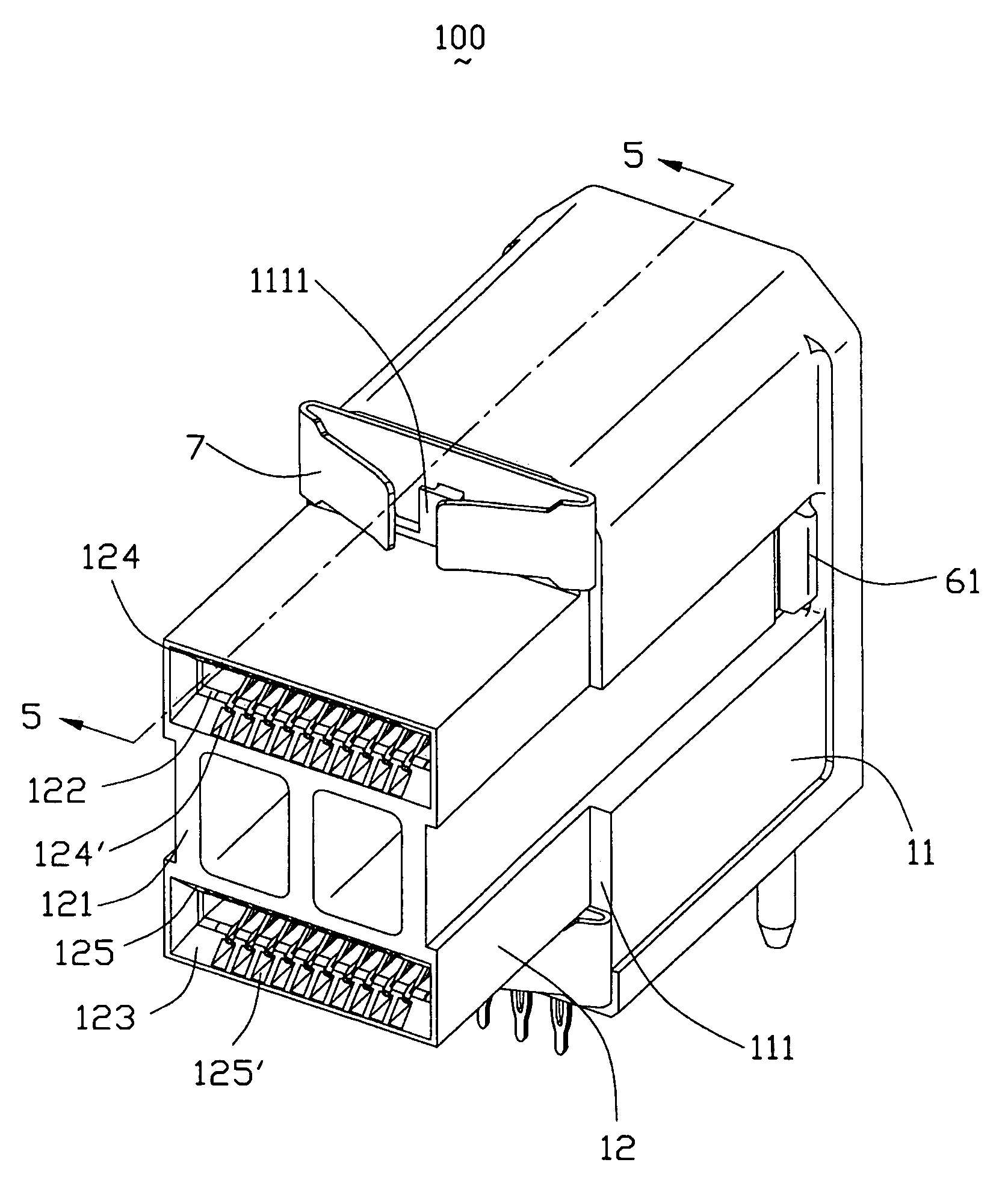
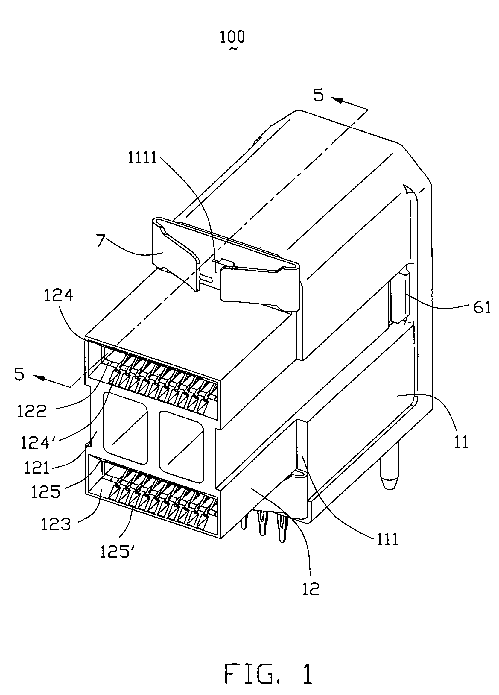
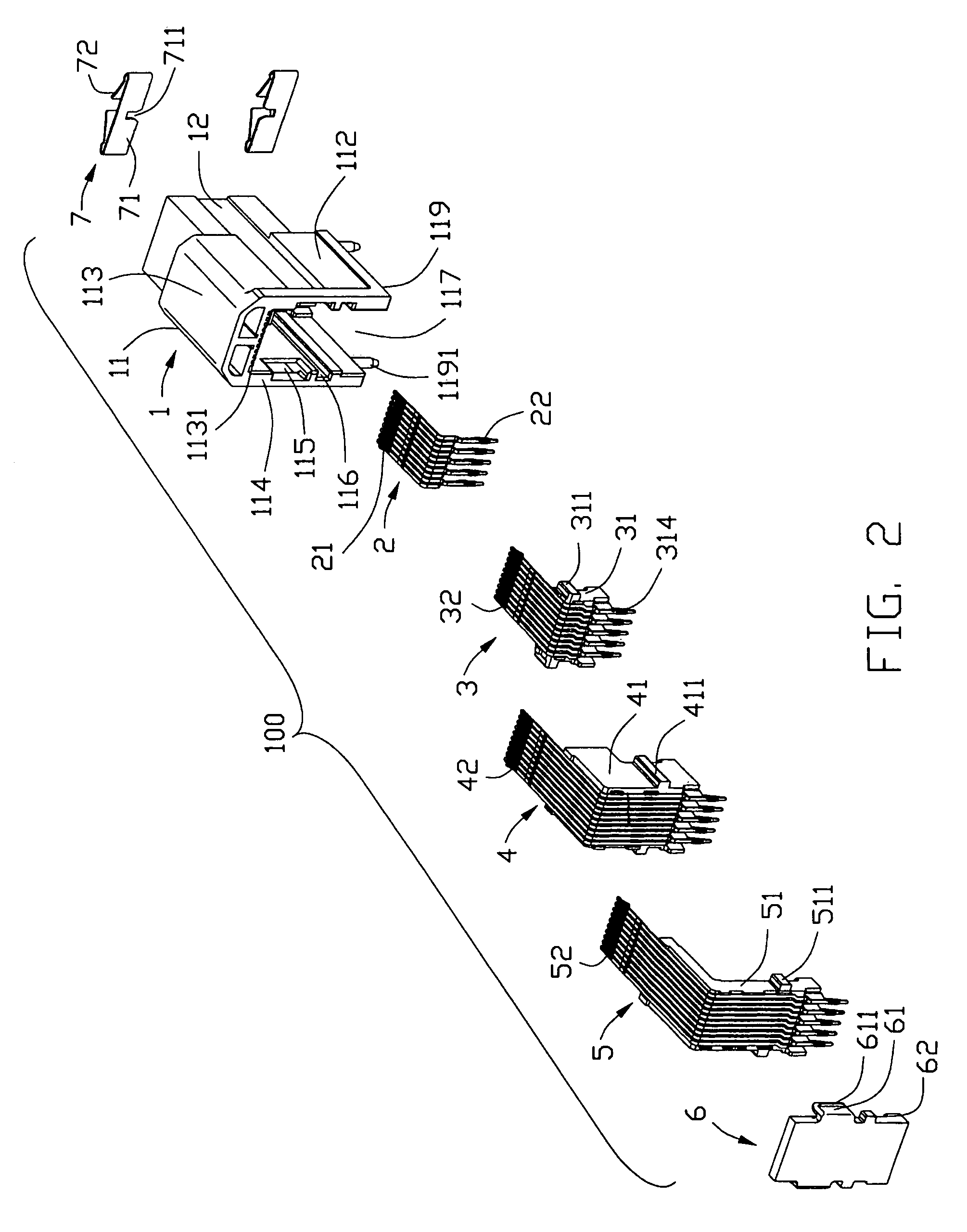
[0019]Referring to FIGS. 1–2, a pluggable connector 100 according to the present invention includes a dielectric housing 1, a contact group 2, a first sub-assembly 3, a second sub-assembly 4, a third sub-assembly 5, a back cover 6 and a pair of spring tabs 7.

[0020]Referring to FIGS. 3–4 in conjunction with FIG. 5, the dielectric housing 1 includes a main body 11 and a mating portion 12 forwardly projecting from the main body 11. The main body 11 includes a front face 111, a pair of side faces 112, a top face 113, a bottom face 119 and a rear face 114. The main body 11 further defines a cavity 117 extending through the rear face 114 and the bottom face 119. The main body 11 is formed with an upper and a lower protrusions 1111 on the front face 111 and respectively adjacent to the top and bottom faces 113, 119 for retaining the spring tabs 7. Each side face 112 defines a cutout 115 adjacent...


PUM


Abstract

A pluggable connector (100) includes a dielectric housing (1), a contact group (2), a first sub-assembly (3), a second sub-assembly (4), a third sub-assembly (5), a back cover (6) and a pair of spring tabs (7). The dielectric housing defines a plurality of ribs (118). The first sub-assembly defines a row of front partitions (312) cooperating with the ribs of the dielectric housing and a row of back partitions (314) respectively positioning in opposite sides thereof. The second sub-assembly defines a row of front partitions (412) cooperating with the back partitions of the second sub-assembly and a row of back partitions (414) respectively positioning in opposite sides thereof. The third sub-assembly (5) defines a row of front partitions (512) cooperating with the back partitions of the second sub-assembly and a row of back partitions (514). The back cover defines a plurality of partitions (63) cooperating with the back partitions of the third sub-assembly.

Description

BACKGROUND OF THE INVENTION[0001]1. Field of the Invention[0002]This invention generally relates to a pluggable connector, and more particularly to a small form pluggable connector used in fiber or copper devices for high speed fiber optical communication.[0003]2. Description of the Prior Art[0004]Various international and industry standards are provided to define electrical connectors and transceivers that are used to interface communication equipment and devices for networking applications. One of the standards is known as a small form-factor pluggable (SFP) transceiver receptacle. The conventional transceiver receptacle includes a pluggable connector and a metal cage for shielding against electromagnetic interference (EMI). The cage, which is significantly larger than the pluggable connector, is dimensioned to receive and guide a transceiver module into mating connection with the pluggable connector. However, each transceiver module is a discrete unit, and it is desired to integr...

Claims


Application Information

Patent Timeline
Patent Type & Authority Patents(United States)
IPC IPC(8): H01R13/60
CPCH01R12/727H01R12/585H01R13/26H01R13/635
Inventor KORSUNSKY, IOSIF R.YI, CHONGBROWN, ROBERTJOHNSON, ROBINEMENHEISER, RICHARD RICKMALEHORN, II, RICHARDBLICHASZ, CHARLESSHIPE, JOANNEHARLAN, TOD
Owner HON HAI PRECISION IND CO LTD
Why Eureka
Try Eureka