Spiral orbit charged particle accelerator and its acceleration method

a particle accelerator and spiral orbit technology, applied in accelerators, klystrons, electric discharge tubes, etc., can solve the problem of limited proton energy accelerated with a moderate size cyclotron of about 200 mev, and achieve the effect of increasing the magnet size and increasing the energy gain

Inactive Publication Date: 2007-08-28
NAT INST OF RADIOLOGICAL SCI
View PDF4 Cites 37 Cited by
  • Summary
  • Abstract
  • Description
  • Claims
  • Application Information

AI Technical Summary

Benefits of technology

[0023]The present invention makes it possible to design a spiral orbit charged particle accelerator that has much higher energy gain than that of a conventional ring cyclotron without increasing the magnet size.

Problems solved by technology

However, a proton energy accelerated with a moderate size cyclotron is limited about 200 MeV because technical problems are encountered when the BR increases.

Method used


Image

  • Spiral orbit charged particle accelerator and its acceleration method
  • Spiral orbit charged particle accelerator and its acceleration method
  • Spiral orbit charged particle accelerator and its acceleration method

Examples


example 1

Constant Accelerating Voltage

[0026]Because the accelerating voltage is constant for radiuses, the energy gain ΔE (Mev / u) for each revolution must satisfy Equation (8)

ΔTp=α·ΔE  (8)

where α is constant given by acceleration condition.

[0027]Thus, the period (Tpn) after n revolutions is given by Equation (9)

Tpn=Tp0−n·ΔTp  (9)

Where Tp0 is the particle revolution period at injection point.

[0028]The energy after n revolutions is given by Equation (10)

En=n·ΔE+E0  (10)

where E0 is the injection energy (Mev / u),

[0029]From Equations (8), (9), (10), (1) and (4), the radial magnetic field distribution that satisfies Equation (7) can be calculated.

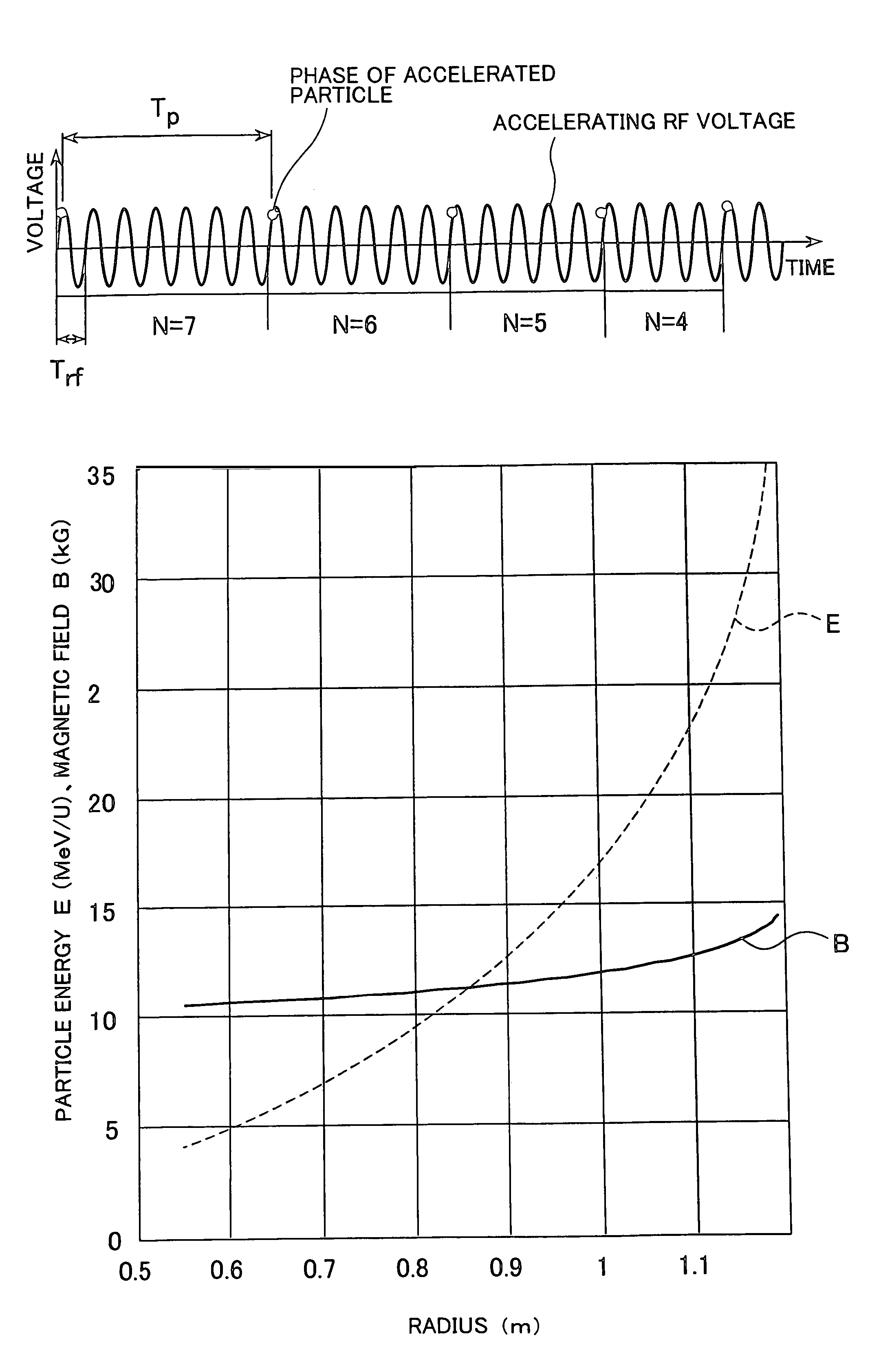
[0030]FIG. 6 shows an example of the spiral orbit charged particle accelerators to which the present invention is applied. In this example, the parameters of acceleration are as follows:

[0031]injection radius: 0.55 m

[0032]extraction radius: 1.19 m

[0033]accelerated ion: C+6

[0034]incident Energy: 4 MeV / u

[0035]extraction energy: 35 MeV / u

[0036]particle revolu...

example 2

[0040]An averaged magnetic field BR at a radius R given by an Equation of BR=BRi (R / Ri)m where Ri is an injection radius and BRi is a magnetic field at the injection radius.

[0041]Because the radial magnetic field distribution is already given, the radial electric field distribution should be determined to satisfy Equation (7).

[0042]The above mentioned magnetic field condition is rewritten by:

B(n)=BRi(R(n) / Ri)m  (11)

where n is the number of particle revolutions, R(n) is the averaged radius at n revolutions, B(n) is the averaged magnetic field at the radius of R(n).

[0043]The every particle revolution period must satisfies Equation (12) as hollows:

Tp(n+1)=Tp(n)−ΔTp  (12)

where n is also the number of particle revolutions, Tp(n+1) is the period of particle revolution at (n+1) particle revolutions, Tp(n) is the period of particle revolution at (n) particle revolutions, and ΔTp satisfies Equation (7).

[0044]From Equations (12) and (1), the change of the particle revolution period ΔTp is giv...

example 3

[0057]When it is difficult to form the accelerating voltage distribution as shown in FIG. 7, a particle accelerator having the same magnetic field distribution as shown FIG. 7 can be designed by modulating the accelerating voltage according to the radius of the accelerated particle. FIG. 8 shows the time dependences of the accelerating voltage and of the particle energy. In this case, the accelerating voltage increases as the particles are accelerated. The obtained energy gain is the just same as that of the example 2 shown in FIG. 7 and further higher than that of example 1 shown in FIG. 6.


PUM


Abstract

According to the present invention, a non-isochronous magnetic field distribution in which the magnetic field increases as the radius increases is formed and a distribution of fixed-frequency accelerating RF voltage is formed, said non-isochronous magnetic field distribution and said distribution of fixed-frequency accelerating RF voltage being formed so that a harmonic number defined as a ratio of the particle revolution period to the period of the accelerating RF voltage decreases in integer for every particle revolution.

Description

CROSS-REFERENCE TO OTHER APPLICATIONS[0001]This is a continuation of prior PCT Patent Application No. PCT / JP2004 / 015989, filed on Oct. 28, 2004, which claims priority from Japanese Patent Application No. 2004-213129, filed on Jul. 21, 2004, each of which is incorporated herein by reference in its entirety.TECHNICAL FIELD[0002]This invention relates to a charged particle accelerator, particularly, relates to a spiral orbit charged particle accelerator and an acceleration method used in the accelerator.BACKGROUND ART[0003]A cyclotron as a typical spiral orbit charged particle accelerator was invented by Lowlence in 1930, and the cyclotron includes a magnet 11 for generating magnetic field, accelerating electrodes 12 for generating radio-frequency (RF) voltage to accelerate charged particles, and an ion source 13 for creating charged particles as shown in FIG. 1-(A) and (B). The magnet 11 includes north pole 15 and south pole 16. The particles are accelerated on the spiral orbit 14.[00...

Claims


Application Information

Patent Timeline
Patent Type & Authority Patents(United States)
IPC IPC(8): H05H7/04
CPCH05H13/00H05H15/00
Inventor FUJISAWA, TAKASHI
Owner NAT INST OF RADIOLOGICAL SCI
Why Eureka
Try Eureka