
Radio detection and ranging intrusion detection system

a radio detection and intrusion detection technology, applied in the field of intrusion detection systems, can solve the problems of affecting the ability of surveillance radar, affecting the ability of lan to transport data without error, and user interference with other users,

Active Publication Date: 2007-08-28
GE SECURITY INC
View PDF21 Cites 13 Cited by
  • Summary
  • Abstract
  • Description
  • Claims
  • Application Information

AI Technical Summary

Problems solved by technology

One complication in using the ISM bands is that the user may interfere with other users, or be interfered with by other users.
The use of RADAR may interfere with the LAN and severely impair the LAN's ability to transport data without error.
Alternatively, the LAN may interfere with the surveillance RADAR's ability to detect intruders at the desired false alarm / missed detection receiver operating characteristic curve.
Building materials and the nature of the building construction may also pose serious operational problems so far as attenuation is concerned.

Method used


Image

  • Radio detection and ranging intrusion detection system
  • Radio detection and ranging intrusion detection system

Examples


Embodiment Construction

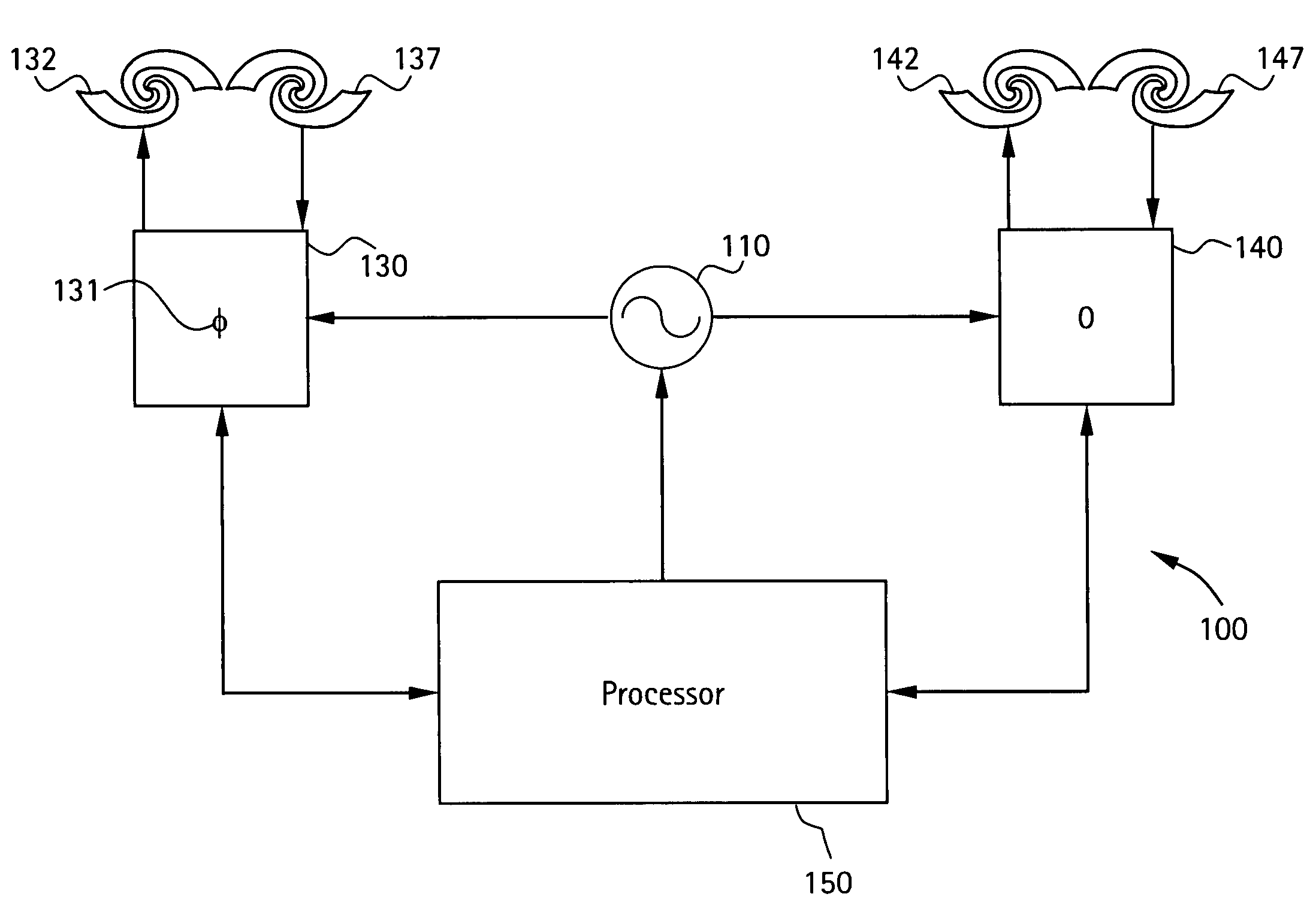
[0009]An embodiment of the invention provides a RADAR system that is capable of operating in two ISM bands and has an aperture consisting of a plurality of radiators that are individually controlled in phase in order to sweep a beam about a monitored area.

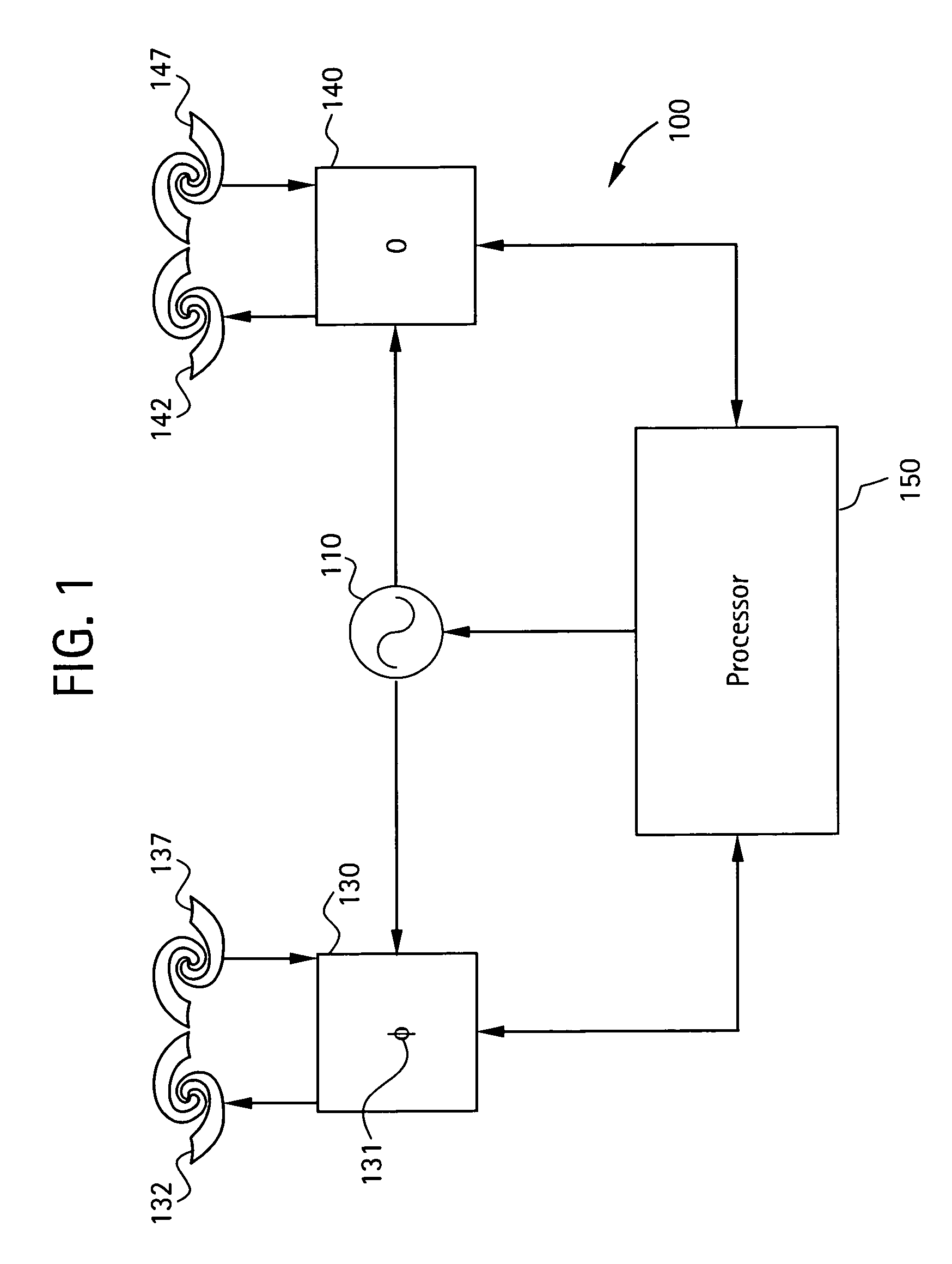
[0010]Referring now to FIG. 1, an exemplary embodiment of a RADAR system 100 is depicted. The system 100 includes a processor 150, a waveform generator 110, a plurality of antenna interfaces 130, 140, a set of first antennas (also herein referred to as transmit antennas) 132, 142, and a set of second antennas (also herein referred to as receive antennas) 137, 147. The waveform generator 110 and the antenna interfaces 130, 140 are each in control and signal communication with the processor 150. The set of first antennas 132, 142 are configured to transmit a waveform, and each of the first antennas 132, 142 are in signal communication with one of each antenna interface 130, 140. The set of second antennas 137, 147 are configured to r...


PUM


Abstract

A radar system having a processor, a waveform generator, a plurality of antenna interfaces, a set of first antennas configured to transmit a waveform, and a set of second antennas configured to receive a reflected waveform is disclosed. The waveform generator and antenna interfaces are in control and signal communication with the processor, each of the first antennas are in signal communication with one of each antenna interface, and each of the second antennas are in signal communication with one of each antenna interface. The waveform generator is in control and signal communication with each antenna interface, and is configurable to generate a waveform conforming to at least two ISM bands. Each first antenna is configured to transmit a circularly polarized electromagnetic waveform, and each second antenna is configured to receive a reflected circularly polarized electromagnetic waveform complementary to the first antennas.

Description

BACKGROUND OF THE INVENTION[0001]The present disclosure relates generally to intrusion detection systems, and particularly to radio detection and ranging (RADAR) intrusion detection systems.[0002]There is a need for security devices to monitor areas subject to penetration by trespassers and also to alert authorities when personnel have entered a hazardous zone. One commonly employed technique is that of electromagnetic RADAR. It is well known in the art that a RADAR system may be used to monitor an area even though there is no direct visible line of sight from the RADAR unit to the area under surveillance, as a RADAR signal may often successfully penetrate and return through common building materials, thereby allowing the RADAR unit to be hidden or inconspicuous.[0003]For an electromagnetic emitter such as a RADAR unit, it is important to select an appropriate frequency band for operation. There are many bands that may be used but most of them require a license for operation. Bands ...

Claims


Application Information

Patent Timeline
Patent Type & Authority Patents(United States)
IPC IPC(8): G01S13/56G01S13/04G01S13/00
CPCG01S7/026G01S13/04H01Q3/26H01Q9/27H01Q21/28H01Q21/29G01S7/2813G01S13/56
Inventor HERSHEY, JOHN ERIKHOCTOR, RALPH THOMASDAVENPORT, DAVID MICHAELASHE, JEFFREY MICHAELFREY, RICHARD LOUISWELLES, KENNETH BRAKELEYSTAUDINGER, V. PAULTOMLINSON, JR., HAROLD W.
Owner GE SECURITY INC
Learn More