
System and method for statistically directing automatic gain control

a technology of automatic gain control and statistical directing, applied in the field of communication interference detection and mitigation systems, can solve the problems of inability to act upon the impulse of the agc, the prior art system is undesirable, and the limit of the prior art ag

Active Publication Date: 2007-08-28
NETGEAR INC
View PDF49 Cites 41 Cited by
  • Summary
  • Abstract
  • Description
  • Claims
  • Application Information

AI Technical Summary

Benefits of technology

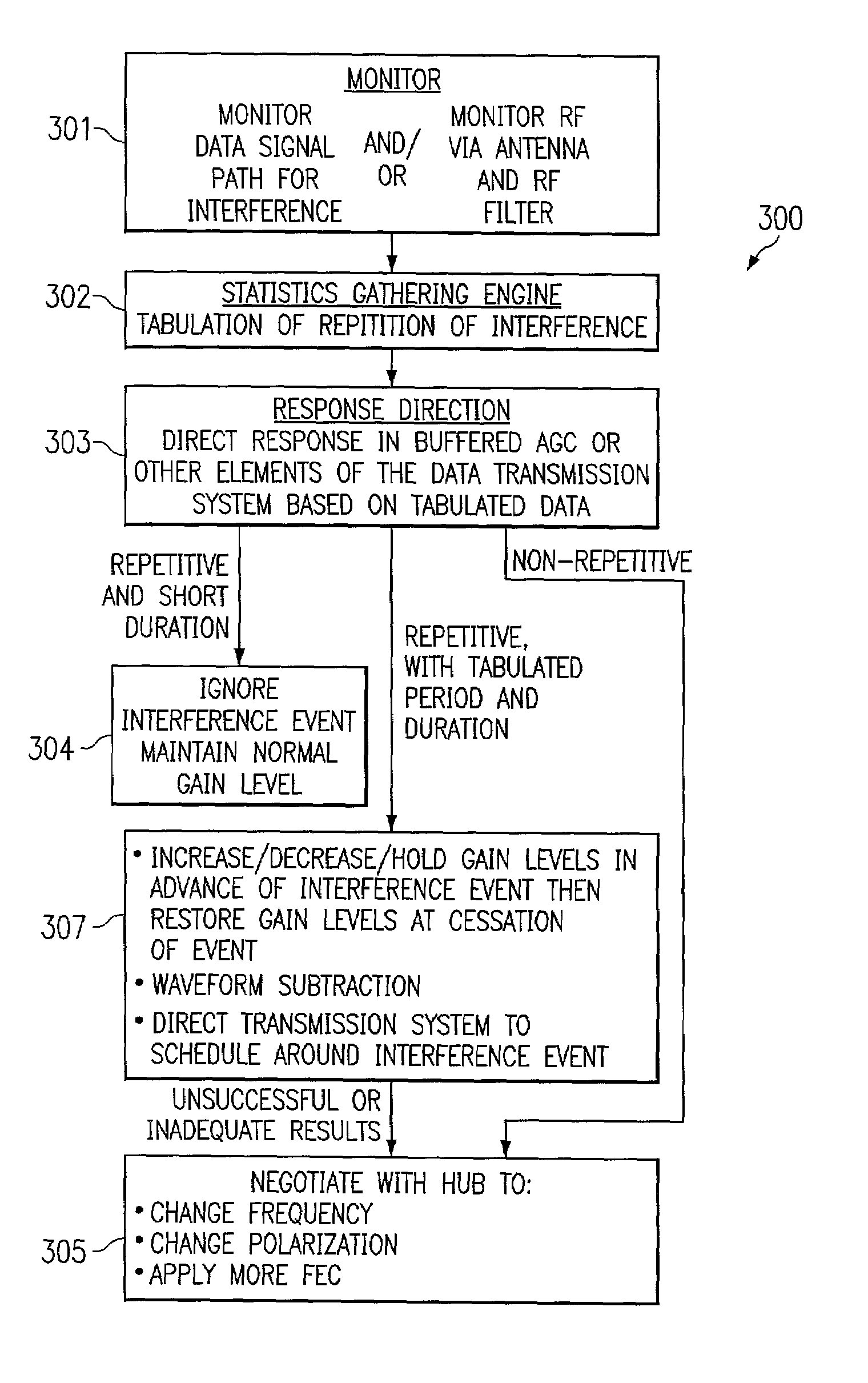
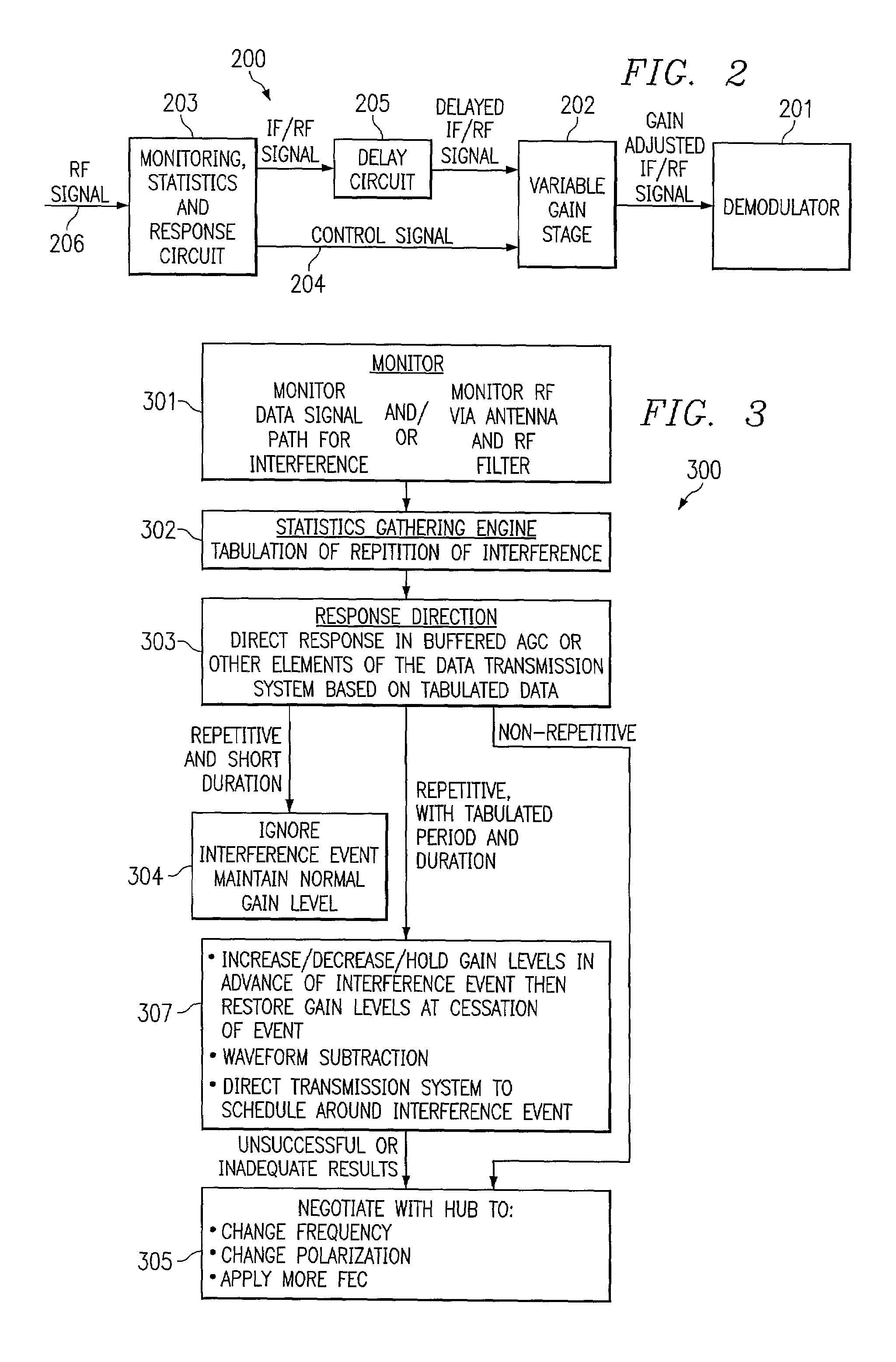
[0016]The present invention is directed to a system and method which provides a solution that statistically determines when regularly occurring interference events of a predictable duration will occur and directs an AGC circuit to respond accordingly. The repetition rate and width of predictable interference, such as radar pulses, are by definition very regular. By averaging and watching for correlations, a statistically guided AGC will be able to identify the pulse rate and pulse widths and be able to predict over a fairly short period of time when the next interference pulse is coming. When the next pulse comes, the AGC can be adjusted just ahead of the pulse to react accordingly. The AGC can adjust gain levels for the duration of the pulse, or ignore the pulse. If a pulse is anticipated to be of a very short duration, the AGC can be directed to ignore the pulse so that the AGC level will coast through the event only losing data for the duration of the pulse.

Problems solved by technology

Prior art AGC has been limited because it has been implemented with an analog servo loop or feedback loop.
This prior art system is undesirable because if an impulse comes through the system, a radar pulse for example, it is too late for the AGC to act upon the impulse.
As a result there is damage to the wave form, and thousands of bits of data are destroyed before the AGC can get around to setting a new level that would accommodate the radar pulse.
If a system could not achieve a low level of interference, a license would not be granted for most systems.
In an unlicensed band, the user is essentially on his / her own and usually no such official remedy is available.
Because of the licensed nature of such RF bands, only a limited number of companies may provide service within those bands.
However, operators are not protected from possible interference from other U-NII operators transmitting in the vicinity or even other systems which utilize the same frequencies.
Equipment that is compatible with this standard may cause interference with use of these unlicensed bands.
One major problem with the use of such unlicensed bands is that it is very difficult, if not impossible, to control RF interference from other users of the unlicensed band.
When the same band is used for point to point communication, and also used by others such as radar, data communications between sending and receiving antennas will experience significant interference from radar pulses, which are broadcast over a wide area in small (narrow) repetitive bursts.
However, there is other low level interference in the unlicensed RF bands.
Therefore, generally speaking, prior art interference mitigation systems do not detect radar interference nor do they attempt to avoid it.
It basically has feedback loops so it monitors what it receives, but by the time it responds to dampen a signal, data is lost.
The prior art AGC is not sufficient for use with RF data transmission in relatively noisy unlicensed bands.
A large amount of in-band interference, and potentially high power interference, such as radar pulses are present in unlicensed RF bands which is very disruptive to high speed data transmissions in those bands.
In an unlicensed RF band data transmission environment it is difficult to determine a proper AGC bandwidth.
If the AGC bandwidth is too low, response is very slow.
However, the AGC may overcompensate, lowering gain levels too quickly or to too low of a level, resulting in lost data.
Prior art AGC will not allow both high gain and low gain settings at the same time.
Ramping very quickly will either raise the gain to an unacceptable level or lower the gain disrupting the transmission rate, which results in a signal which cannot be properly modulated / demodulated.

Method used


Image

  • System and method for statistically directing automatic gain control
  • System and method for statistically directing automatic gain control
  • System and method for statistically directing automatic gain control

Examples


Embodiment Construction

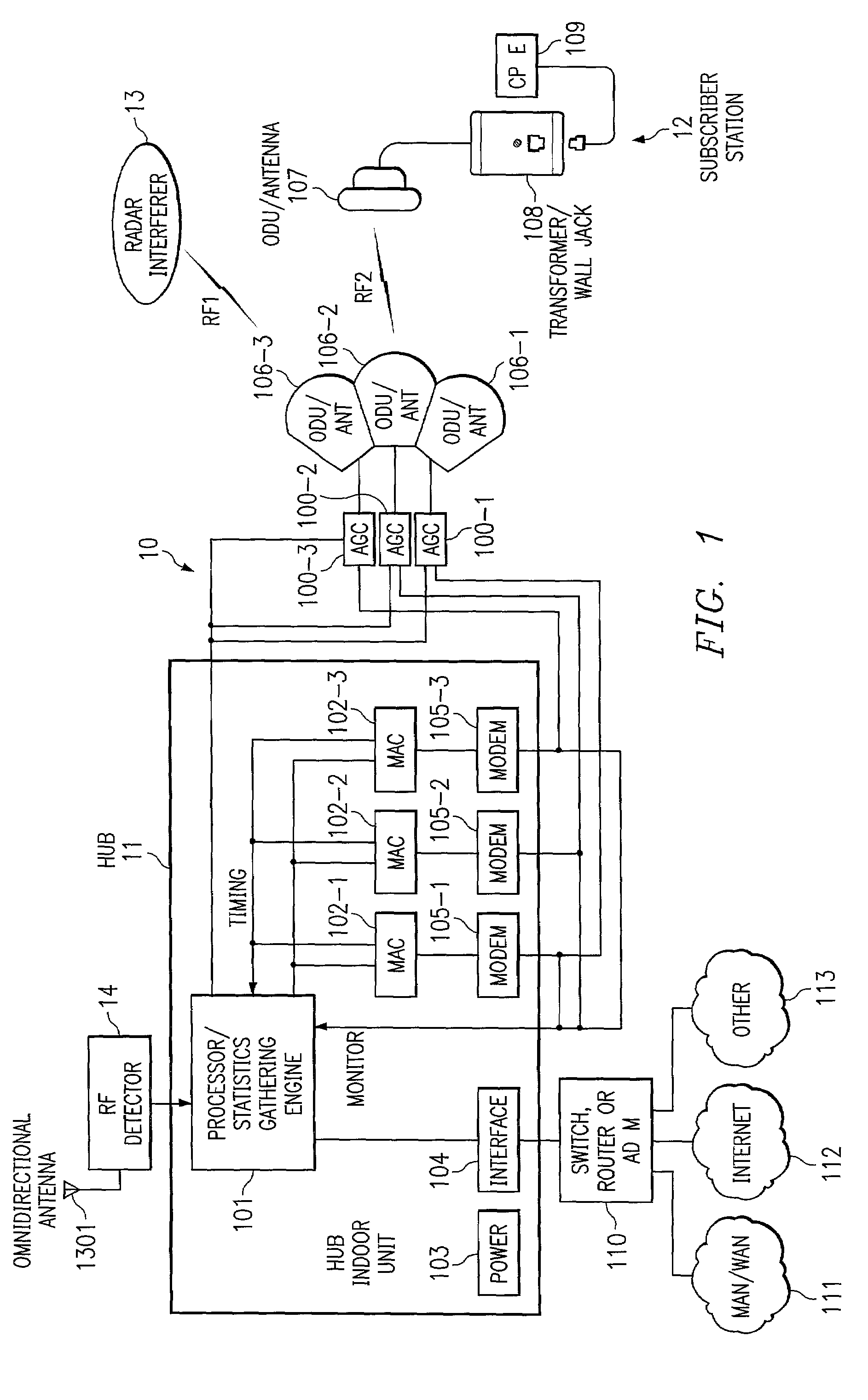
[0022]The present invention is used to detect interference and mitigate its effect on data transmission in unlicensed RF bands employing a method and system for a statistically directed automatic gain control 100 (AGC). Turning to FIG. 1, data transmission system 10 has hub 11 (which could be one of many) and subscriber station (SS) 12, again one of many. Hub 11 would be connected in a typical installation to other remotely located subscribers or users (not shown) via one or more networks, such as MAN / WAN 111, Internet 112, or any other network, such as network 113, all via switch router and / or add drop multiplexer ADM 110 and interface 104. These networks could be internal to an enterprise or could be connected to public or private networks either directly or via an intermediary network. Power for the hub 11 is provided via power supply 103.

[0023]Hub 11 serves to direct communications between subscriber station 12 and other users over RF link RF2 between one or more hub antennas 10...


PUM


Abstract

The present invention is directed to a system and method which statistically determines when regularly occurring interference events of a predictable duration will occur, for example radar pulses and dynamically adjusts an automatic gain control (AGC) for RF data transmissions accordingly. The repetition rate and width of radar pulses are regular. By averaging and watching for correlations, the present AGC identifies the pulse rate and pulse widths and over a fairly short period of time predicts when the next pulse is coming. When the next pulse occurs, the AGC is adjusted to react accordingly. The AGC can raise or lower gain levels for the duration of the pulse; or ignore the pulse, if it is of a very short duration, so that the AGC level will coast through the event.

Description

TECHNICAL FIELD OF THE INVENTION[0001]The present invention relates to communications interference detection and mitigation systems and more particularly to a system and method for directing automatic gain control for RF data transmissions in response to tabulated interference statistics.BACKGROUND OF THE INVENTION[0002]Automatic Gain Control (AGC) is used in virtually all radio receivers, and serves several functions. Primarily AGC is necessary to keep signal levels within a range so that a system's amplifiers are not overloaded. AGC serves to maintain proper tracking loop gain for servos and maintain levels that are appropriate for demodulation. Many modulation formats, such as 64QAM and 16QAM, need to adjust the signal level fairly accurately in order for the demodulator to deliver a usable data stream.[0003]Prior art AGC has been limited because it has been implemented with an analog servo loop or feedback loop. For example, a signal may arrive at the demodulator and feed back t...

Claims


Application Information

Patent Timeline
IPC IPC(8): H04L27/08H03D1/04H04B1/06
CPCH03G3/3052
Inventor ROTHAAR, BRUCE C.PRISMANTAS, JERRYKARR, RANDY J.GRENON, JEAN-FRANCOISA'NYEHOLT, HEINZ LYCKLAMA
Owner NETGEAR INC
Learn More