Apparatus and method for controlling driving force supplied to wheels on opposite sides of vehicle

a technology of driving force and apparatus, which is applied in the direction of gearing, instruments, tractors, etc., can solve the problem that the distribution control of driving force sometimes does not achieve sufficient

Active Publication Date: 2007-08-28
MITSUBISHI MOTORS CORP
View PDF39 Cites 14 Cited by
  • Summary
  • Abstract
  • Description
  • Claims
  • Application Information

AI Technical Summary

Benefits of technology

[0019]As another preferable feature, the control amount adjusting device may decrease a first control gain of the first controlling device in accordance with an increase in an index indicating an understeer state, and may decrease a second control gain of the second controlling device in accordance with an increase in an index indicating an oversteer state.
[0020]As an additional preferable feature, the control amount adjusting device may decrease a first control gain of the first controlling device to a predetermined value when an index indicating an understeer state is in excess of a predetermined value, and may decrease a second control gain of the second controlling device to a predetermined value when an index indicating an oversteer state is in excess of a predetermined value.
[0021]As a further preferable feature, the control amount adjusting device may set a first gain of the first controlling device and a second gain of the second controlling device such that a sum of the first gain and the second gain is a constant value.

Problems solved by technology

However, a simple combination of the left-right wheel speed difference feedback control and the yaw rate feedback control may output control signals (control amounts) for inverse controls when a vehicle is in some states, so that the control signals offsets the effects of the both of the controls and driving force distribution control sometimes does not achieve sufficient effect.

Method used


Image

  • Apparatus and method for controlling driving force supplied to wheels on opposite sides of vehicle
  • Apparatus and method for controlling driving force supplied to wheels on opposite sides of vehicle
  • Apparatus and method for controlling driving force supplied to wheels on opposite sides of vehicle

Examples


Embodiment Construction

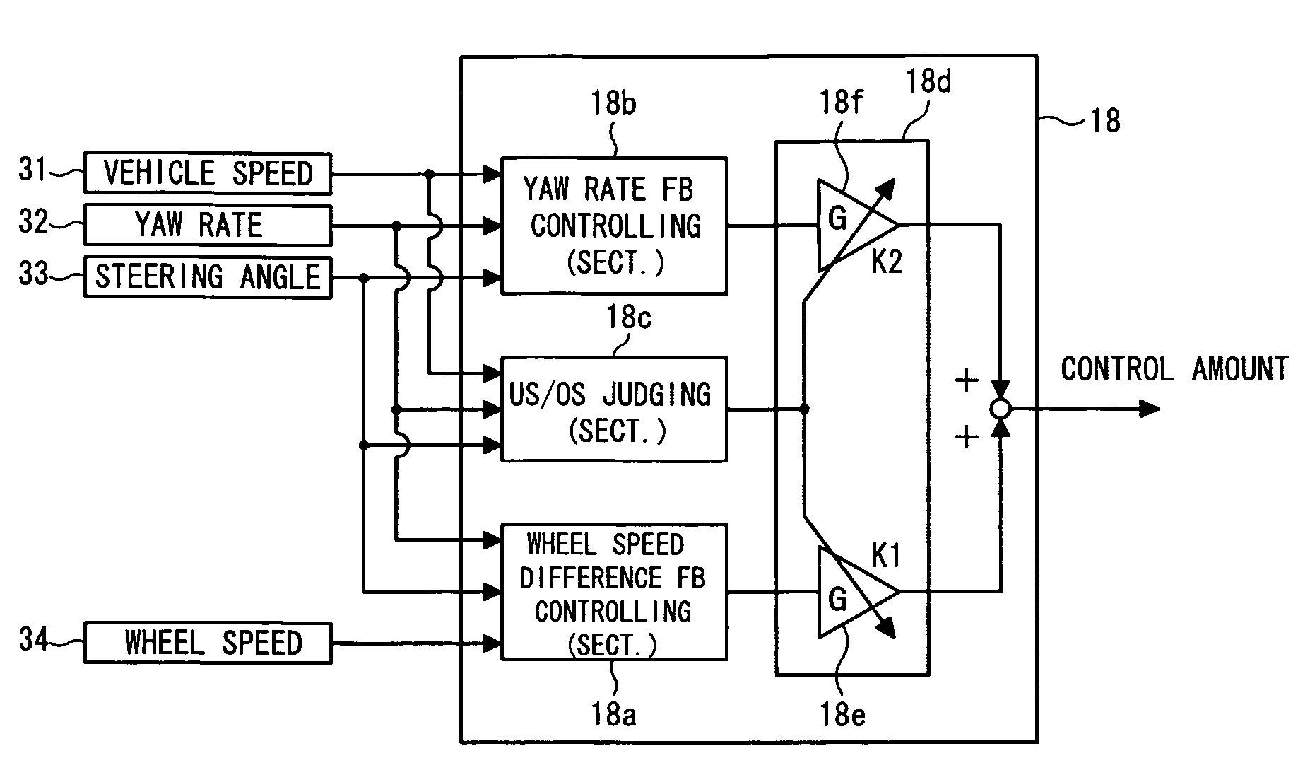
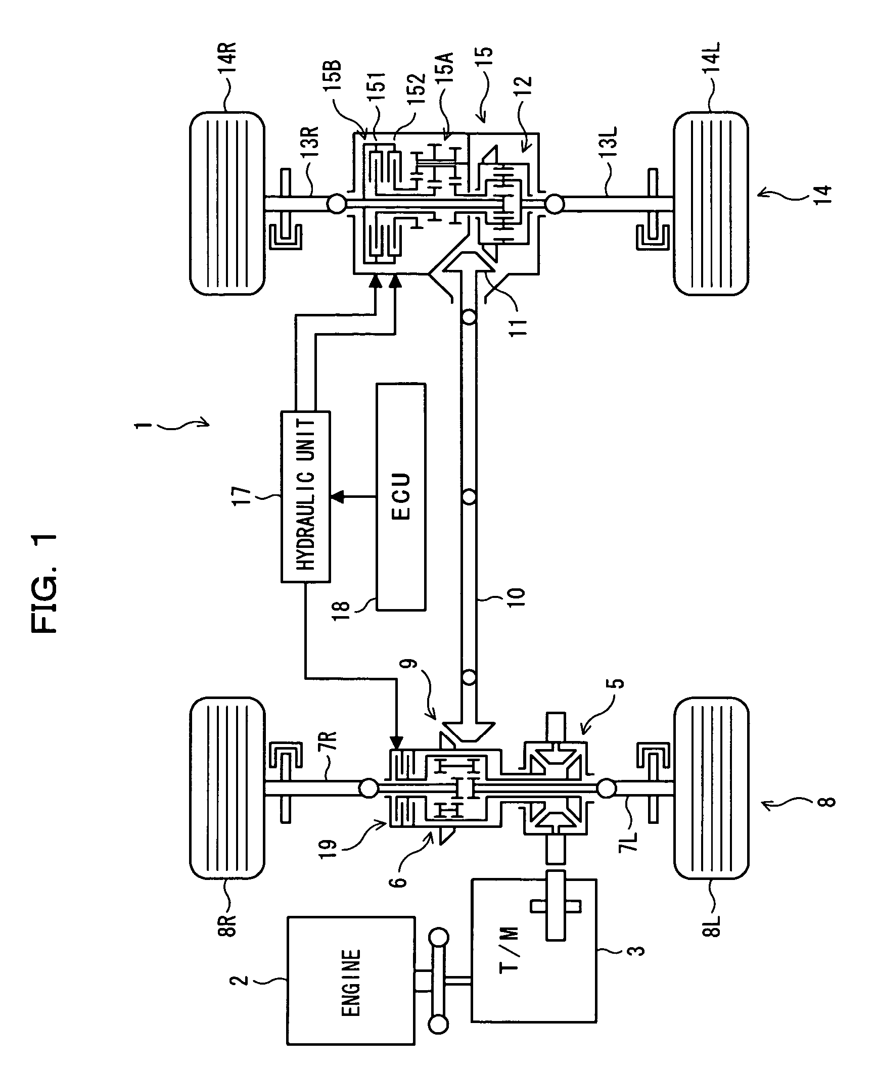
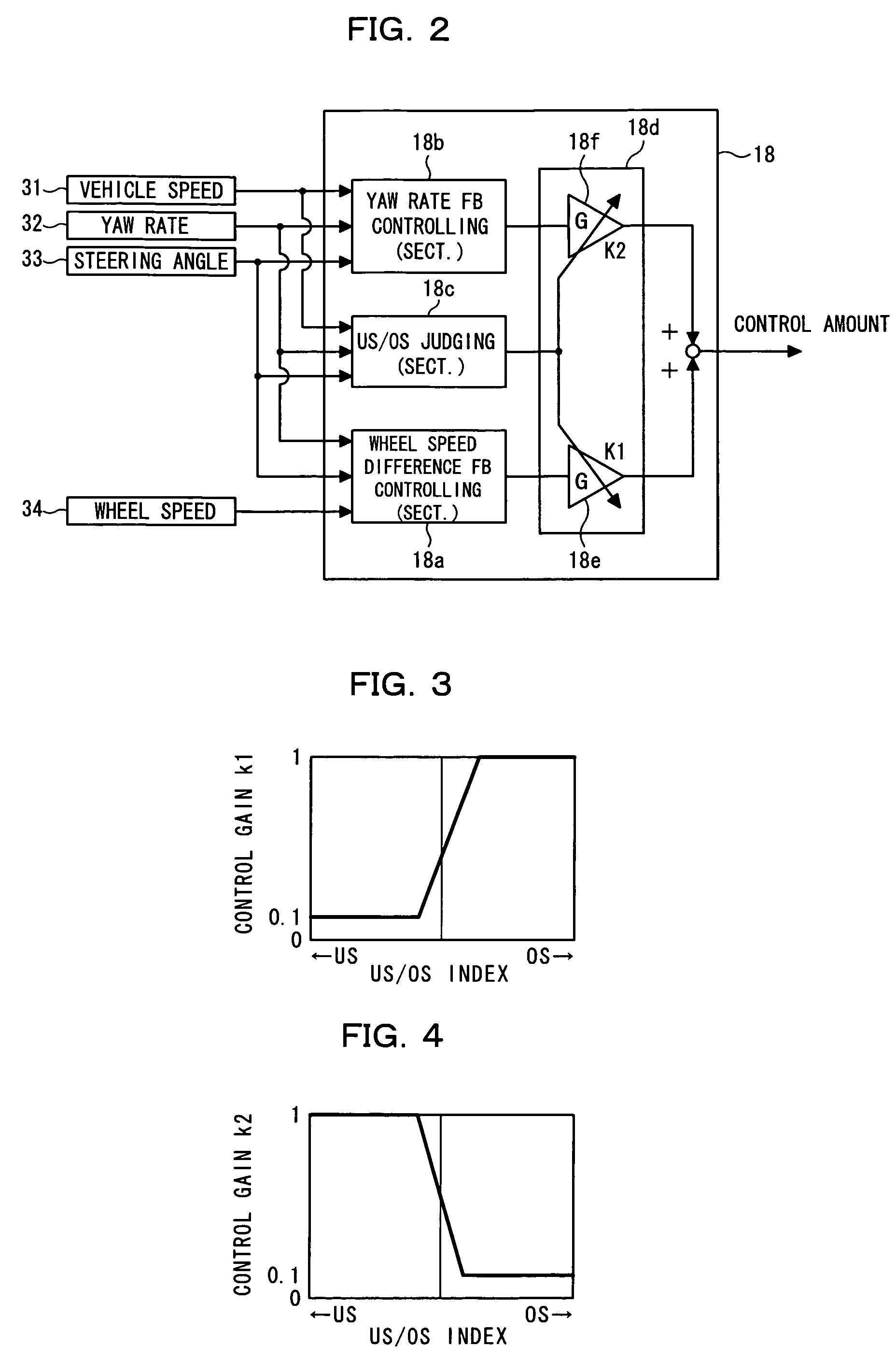
[0031]An apparatus for controlling driving force supplied to the left and right wheels according to an embodiment of the present invention will now be described with reference to the accompanying drawings. FIG. 1 schematically illustrates a vehicle to which the present invention is applied; FIG. 2 schematically shows the main part of the present invention; and FIGS. 3 and 4 are maps respectively showing characteristics of control gains of the present invention.

[0032]In FIG. 1, reference numbers 1, 2, and 3 represent a vehicle to which the present invention is applied, an engine, and a transmission, respectively. Power generated by the engine 2 is passed to a center differential (hereinafter called a center diff) 5 via the transmission 3. The center diff 5 divides the received power and supplies each of front wheels 8 and rear wheels 14.

[0033]Specifically, a portion of the power input to the center diff 5 is further sent to a front differential (hereinafter front diff) 6 and is passe...


PUM


Abstract

An apparatus for controlling driving forces supplied to left and right wheels of a vehicle, for effectively inhibiting oversteer and understeer states, includes driving force adjusting device for adjusting driving forces supplied to the left and the right rear wheels, first controlling device for controlling the driving force adjusting device such that a wheel speed difference between the left and the right rear wheels coincides with a target wheel speed difference, and second controlling device for controlling the driving force adjusting device such that a yaw momentum of the vehicle coincides with a target yaw momentum. If the vehicle is in an understeer state, the contribution of the second controlling device is increased relative to that the first controlling device and if the vehicle is in an oversteer state, the contribution of the first controlling device is increased relative to that of the second controlling device.

Description

BACKGROUND OF THE INVENTION[0001]1. Field of the Invention[0002]The present invention relates to an apparatus and a method for controlling driving forces supplied to left and right wheels of a vehicle.[0003]2. Description of the Related Art[0004]Conventionally, a technique that changes the driving force to be supplied to each of left and right wheels has been known (e.g., reference 1: Japanese Patent Application Laid-Open (KOKAI) publication number 2002-114049, and reference 2: Japanese Patent number 3114457). Such a technique arranges a driving force distribution mechanism along with the differential gear between a left driving wheel and a right driving wheel and controls the driving force distribution mechanism to thereby control driving force to be supplied to each of the wheels.[0005]The following two feedback controls are typically applied to a driving force supply mechanism.[0006]1. left-right wheel speed difference feedback control:[0007]A target wheel speed difference betwee...

Claims


Application Information

Patent Timeline
Patent Type & Authority Patents(United States)
IPC IPC(8): G06F7/00G06F17/00B60K23/04F16H48/06F16H48/20F16H48/32F16H48/36
CPCB60K23/04B60W30/02B60W2520/14B60W2520/28B60W2720/14B60W2540/18B60K17/344
Inventor MOTOYAMA, SUMIO
Owner MITSUBISHI MOTORS CORP
Why Eureka
Try Eureka