System and method for three-dimensional visualization and postprocessing of a system model

a system model and three-dimensional visualization technology, applied in the field of system modeling, can solve the problems of not including the capability for 3d visualization needed to understand and verify the parameter settings and symbol connectivity of non-electrical structures like mems, and the difficulty of network simulation interpretation, and the insufficient x-y plo

Active Publication Date: 2007-08-28
COVENTOR
View PDF0 Cites 19 Cited by
  • Summary
  • Abstract
  • Description
  • Claims
  • Application Information

AI Technical Summary

Problems solved by technology

Unfortunately, there are a number of drawbacks to the application of CAD systems originally intended for IC design to the MEMS design process.
While conventional IC design tools allow the user to extract a two-dimensional layout from a schematic, they do not include the 3D visualization capability needed to understand and verify the parameter settings and symbol connectivity of non-electrical structures like MEMS.
Additionally, conventional methods of visualizing schematic designs of a model make it difficult to interpret network simulation results.
These X-Y plots are not sufficient, however, for understanding the motion of a complex MEMS that may consist of tens or hundreds of individual mechanical components and / or multiple optical beams.

Method used


Image

  • System and method for three-dimensional visualization and postprocessing of a system model
  • System and method for three-dimensional visualization and postprocessing of a system model
  • System and method for three-dimensional visualization and postprocessing of a system model

Examples


Embodiment Construction

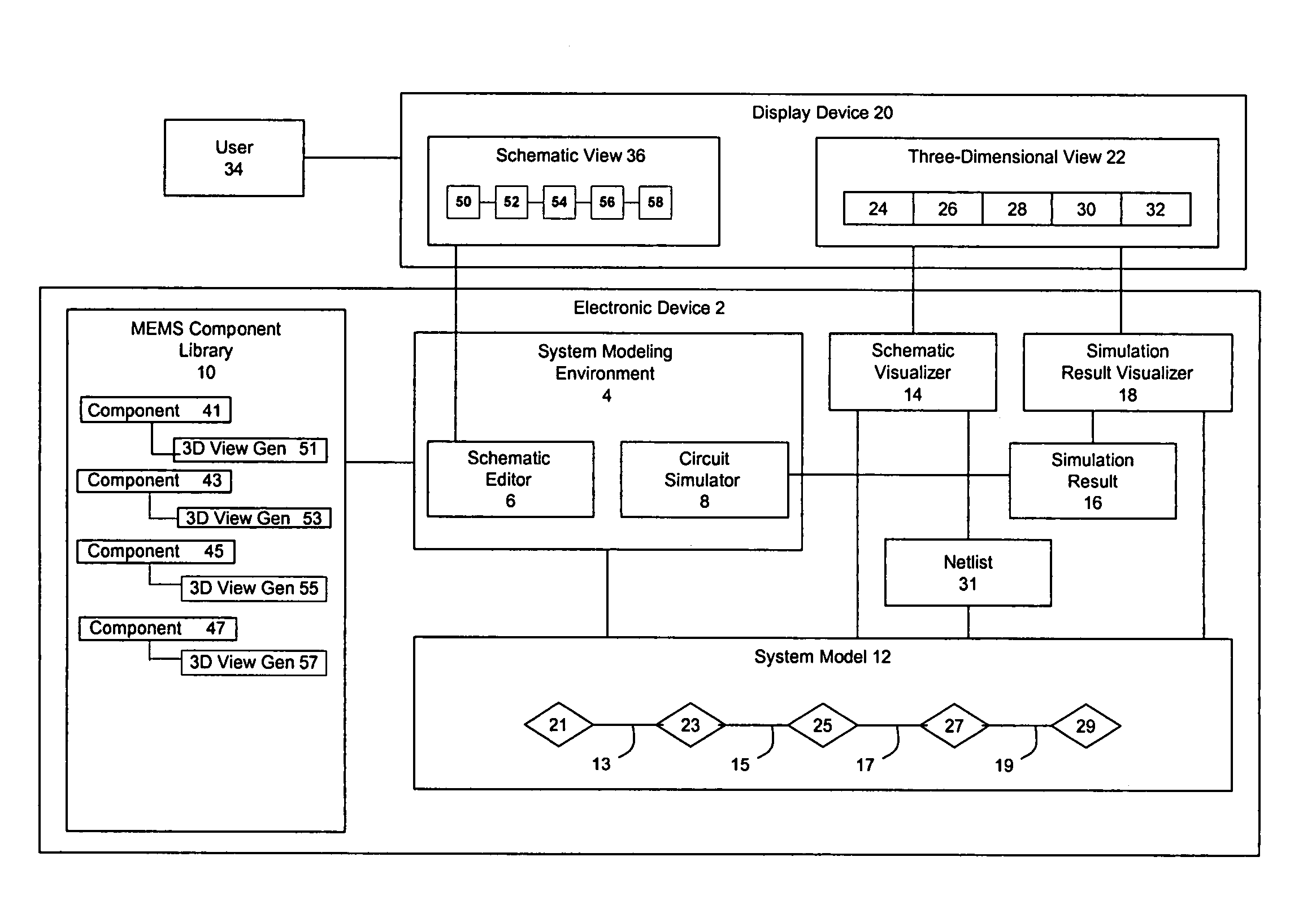
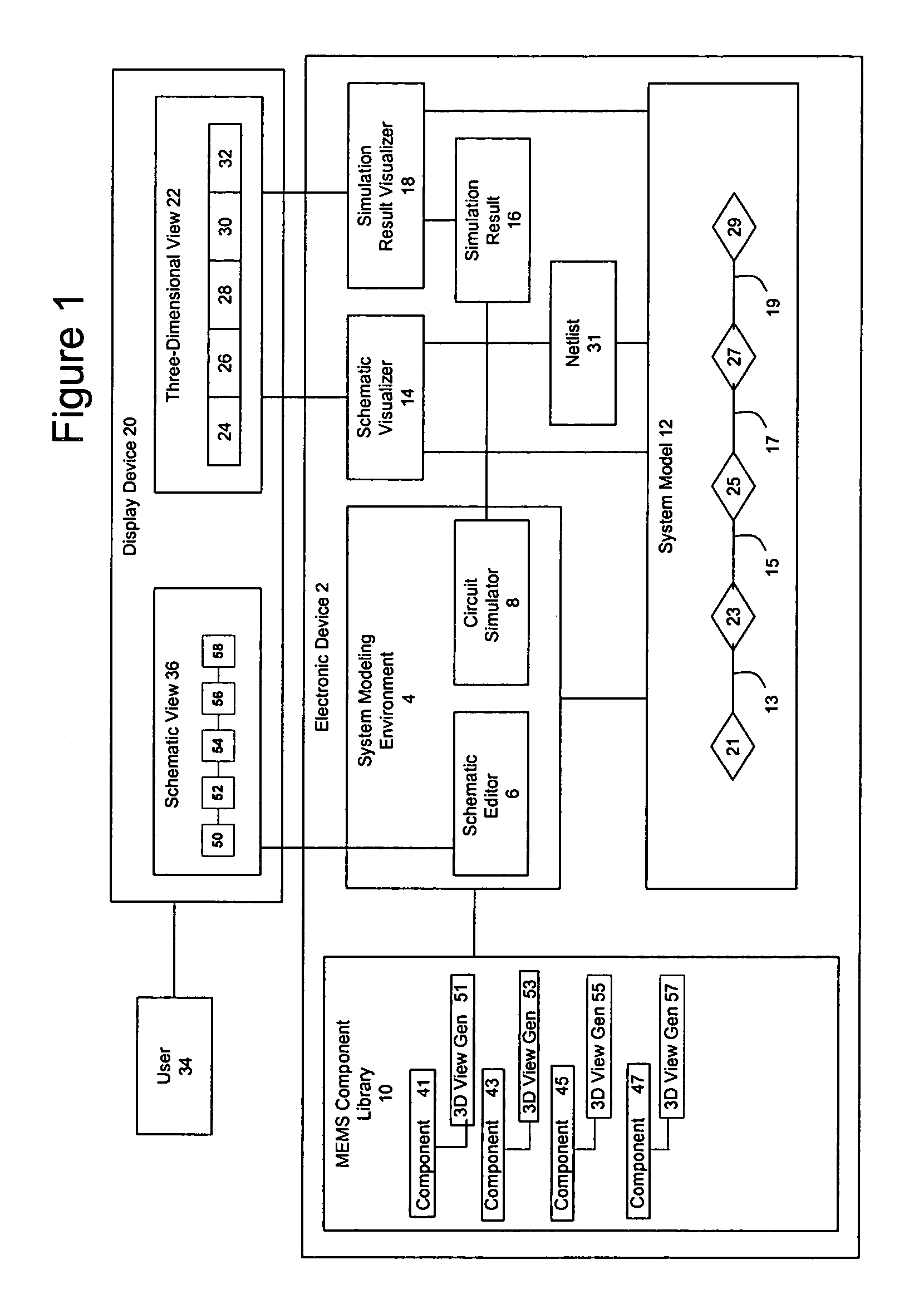
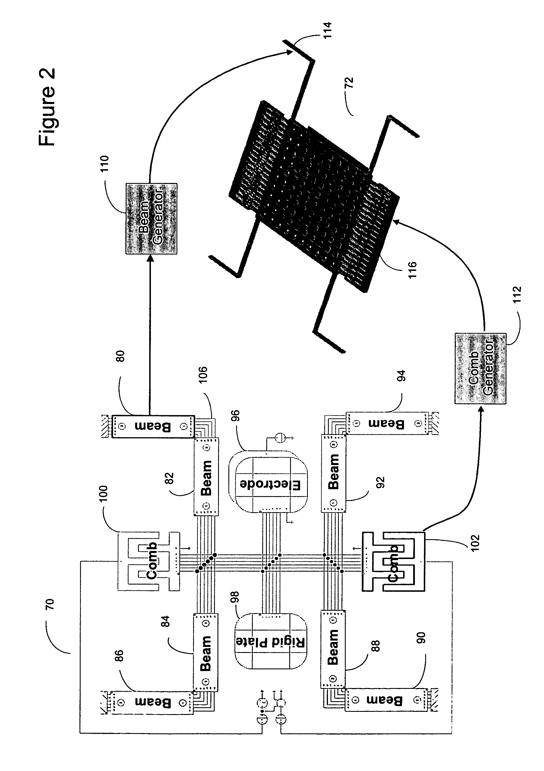
[0019]The illustrative embodiment of the present invention enables the generation of a graphical three-dimensional (3D) view of a Micro Electro-Mechanical System (MEMS) model captured in a schematic. Information contained in the MEMS model is used to generate 3D views of model components that collectively compose an overall 3D view. The MEMS schematic holds mathematical representations of MEMS model components selected from a MEMS model library. The MEMS model components include parameter information and include or reference 3D view generators used to generate the 3D view of the associated part. The MEMS model is programmatically analyzed to identify the associated 3D view generators used to generate the 3D views of the components. Connection information from the MEMS model is leveraged to connect the individual 3D views of the components. The visualization process may be extended so to include a simulator that simulates the underlying MEMS model. The simulation results are then dis...


PUM


Abstract

The generation of a graphical three-dimensional (3D) view of a system model of a Micro Electro-Mechanical System (MEMS), which also may be depicted in a schematic view, is disclosed. Information contained in the system model is used to generate 3D representations of model components which are then assembled into an overall model. The system model is composed by selecting MEMS component models from a MEMS component library. The MEMS component models include parameter information and include or reference 3D view generators used to generate the 3D view of the associated component. The system model is programmatically analyzed to identify the associated 3D view generators used to generate the 3D views of the components. The visualization process may be extended to include a simulator which simulates the underlying system model. The simulation results are then displayed by using the 3D visualization process to present 3D views of the model as it changes during different points in the simulation.

Description

FIELD OF THE INVENTION[0001]The illustrative embodiment of the present invention relates generally to system modeling and more particularly to the three-dimensional (3D) visualization and post-processing of a system model of a MEMS device.BACKGROUND[0002]Computer Aided Design (CAD) systems are used to design and simulate virtual models of electrical, electronic or mechanical devices prior to producing actual physical devices. CAD systems are interactive software tools that run on a digital computer with a graphical display device. In particular, micro-fabricated devices such as electronic integrated circuits (ICs) and Micro Electro-Mechanical Systems (MEMS) can be designed and simulated virtually using CAD systems prior to beginning the costly and time-consuming process of fabricating the actual physical devices.[0003]MEMS are micro- or nano-scale devices typically fabricated in a similar fashion as integrated circuits (ICs) to exploit the miniaturization, integration, and batch pro...

Claims


Application Information

Patent Timeline
Patent Type & Authority Patents(United States)
IPC IPC(8): G06F17/10G06F17/50G06G7/48B81B7/02
CPCG06F17/5009G06F17/5045G06F17/5086G06F2217/16G06F2217/74G06F30/30G06F30/17G06F2111/12G06F2111/10G06F30/20G06F30/3308G06F2115/04
Inventor LORENZ, GUNAR
Owner COVENTOR
Why Eureka
Try Eureka