Butterfly valve assembly with improved flow characteristics

a butterfly valve and flow characteristic technology, applied in valve housings, machines/engines, mechanical equipment, etc., can solve the problems of cavitation-induced damage in liquid service, noise in gas service, and inability to utilize this diffuser in other valves, and achieve the effect of enhancing the full flow fluid characteristics of the valve assembly and enhancing the controllability of the butterfly valv

Active Publication Date: 2007-09-04
YEARY & ASSOCS
View PDF20 Cites 31 Cited by
  • Summary
  • Abstract
  • Description
  • Claims
  • Application Information

AI Technical Summary

Benefits of technology

[0008]The present invention is related to a control valve assembly that provides enhanced flow characteristics for a butterfly valve during the initial opening of the valve disc. The increased controllability of the flow characteristics for the butterfly valve allows the butterfly valve to function as a more accurate and controllable control valve, similar to the operation of a globe valve.
[0011]The control valve assembly includes a flow insert that is positioned along a portion of the generally cylindrical outer wall that defines the open passageway through the valve body. Preferably, the flow insert is positioned on one side of the pivot shaft axis and in general alignment with the first outer sealing edge of the valve disc such that when the valve disc moves away from the seated position, the first outer sealing edge remains in close proximity to the flow insert as the valve disc rotates. The flow insert restricts the flow of fluid past the first outer sealing edge during the initial movement of the valve disc from the seated position. At the same time, fluid flows past the second outer sealing edge, which allows for better control of the flow through the butterfly valve.
[0013]Although not required, the control valve assembly can include an upstream butterfly cage and a downstream butterfly cage to enhance the controllability of the butterfly valve. The upstream butterfly cage includes at least a pair of openings that allow fluid to flow through the butterfly cage and into contact with the moving valve disc. Likewise, the downstream butterfly cage includes an opening that allows fluid to flow through the downstream butterfly cage as the valve disc moves away from the seated position. Preferably, each of the upstream and downstream butterfly cages includes a center crossbar that enhances the full flow fluid characteristics of the valve assembly.

Problems solved by technology

One of the basic problems for butterfly valves is that this pressure drop tends to cause cavitation and consequent cavitation-induced damage in liquid service and noise in gas service.
For example, one such diffuser is integrally incorporated into the valve element such that it is not possible to utilize this diffuser in other valves.
In addition, butterfly valves are generally not good control valves near the closed or fully opened positions of the valve.
Since butterfly valves are notoriously uncontrollable at the ends of their actuation ranges, butterfly valves are not used in situations where accurate control is necessary.
However, globe and segmented ball control valves are typically much larger and more expensive than butterfly valves.

Method used


Image

  • Butterfly valve assembly with improved flow characteristics
  • Butterfly valve assembly with improved flow characteristics
  • Butterfly valve assembly with improved flow characteristics

Examples


Embodiment Construction

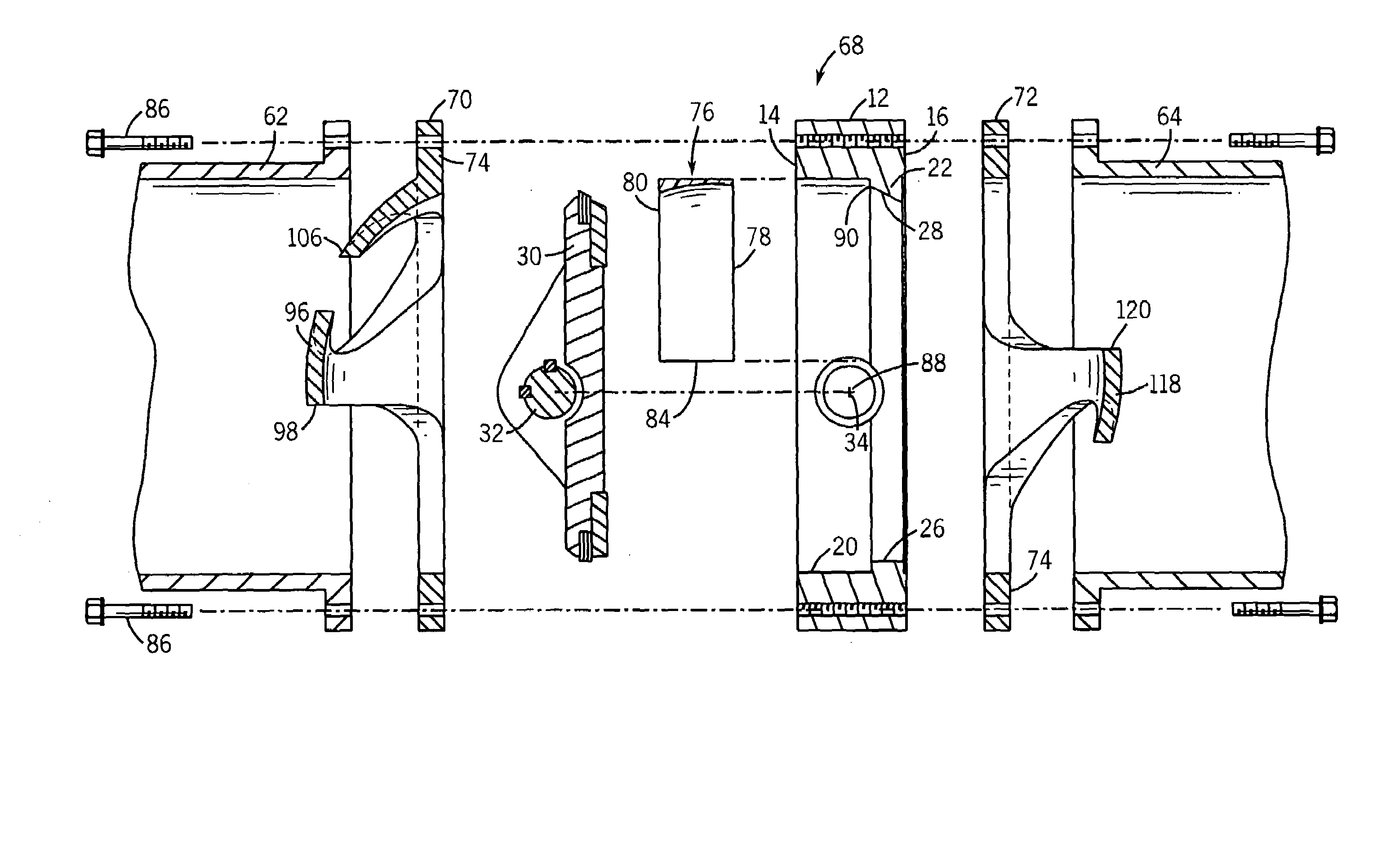
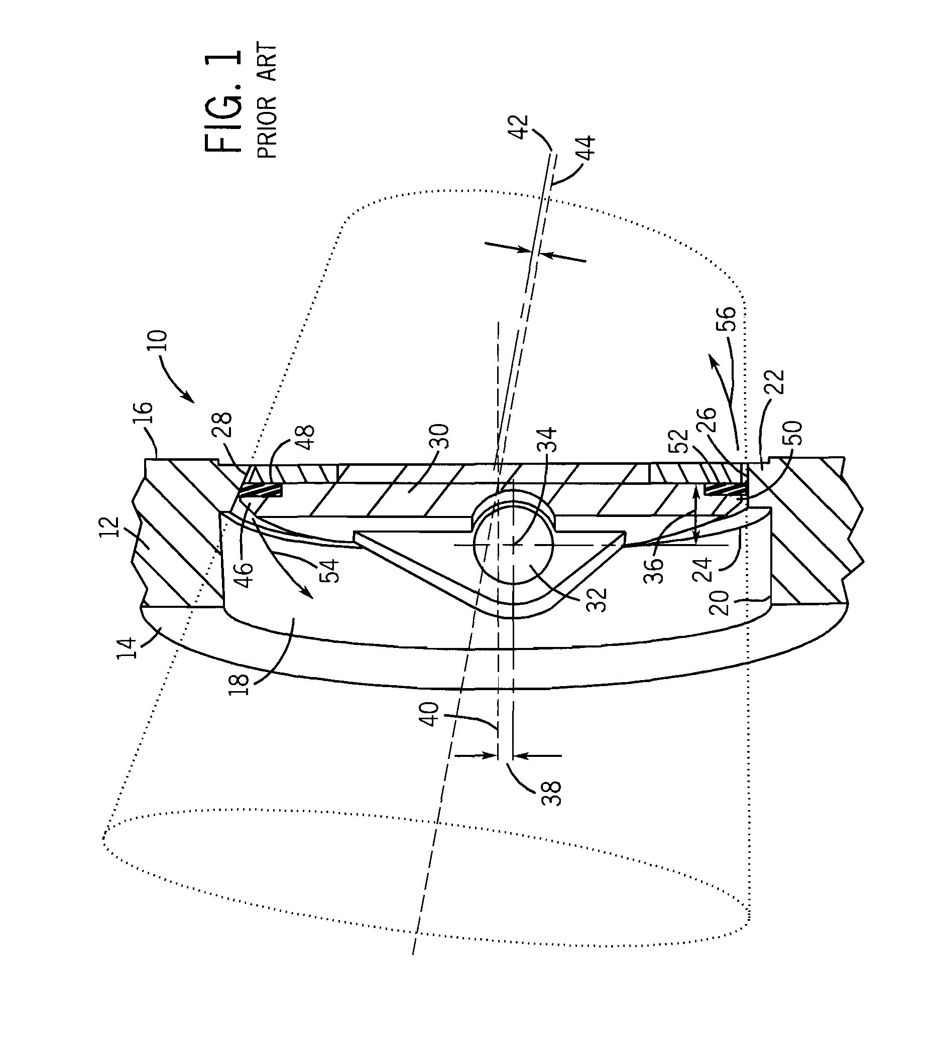
[0027]FIG. 1 illustrates a conventional, triple offset butterfly valve 10. The butterfly valve 10 includes a valve body 12 that extends from an upstream face surface 14 to a downstream face surface 16 and is preferably formed from a metallic material, such as stainless steel. The valve body 12 defines an open passage 18 that allows fluid to flow through the valve body 12 from the upstream face surface 14 to the downstream face surface 16. The open passage 18 is defined by a generally cylindrical outer wall 20. The valve body 12 defines a valve seat 22 that extends radially inward from the outer wall 20 and is defined by an inner shoulder 24. As illustrated in FIG. 1, the valve seat 22 includes both a flat sealing surface 26 and an angled sealing surface 28. In general, the flat sealing surface 26 and the angled sealing surface 28 transition into each other along the circumference of the valve seat. Specifically, as the angled sealing surface 28 extends around the circumference of th...


PUM


Abstract

A control valve assembly that utilizes a butterfly valve having a valve body and a valve disc movable between a seated position and an open position. The control valve assembly includes a flow insert positioned along the interior of the valve body and generally aligned with a first outer sealing edge of the rotatable valve disc. The flow insert maintains close spacing to the first outer sealing edge of the valve disc as the valve disc initially moves away from the valve seat. The control valve assembly can also include a first, upstream butterfly cage and a second, downstream butterfly cage positioned on opposite sides of the valve body. The first and second butterfly cages aid in controlling the flow of fluid past the valve disc as the valve disc moves from its seated position to its open position.

Description

BACKGROUND OF THE INVENTION[0001]Butterfly valves are in common usage for controlling the flow of various fluids, i.e., liquid or gas, streams. Butterfly valves are used to throttle fluid flow and for on / off applications. A typical valve assembly of this type includes a body having a passage extending through it and a butterfly valve vane pivotally mounted within the body. The butterfly vane is characteristically in the form of a disc.[0002]When fluid passes through a partially open butterfly valve, the fluid undergoes a significant pressure drop. One of the basic problems for butterfly valves is that this pressure drop tends to cause cavitation and consequent cavitation-induced damage in liquid service and noise in gas service.[0003]In an attempt to solve these problems, it has been proposed to utilize a diffuser. A diffuser is a perforated member that increases the restriction near the valve opening and breaks the fluid stream into multiple jets. This has a positive effect on the ...

Claims


Application Information

Patent Timeline
Patent Type & Authority Patents(United States)
IPC IPC(8): F16K47/00F16L55/02
CPCF16K1/22F16K1/222F16K27/0218
Inventor YEARY, ARTHUR R.KIELAR, AARONZMICK, ADAMBARDELLI, MATT
Owner YEARY & ASSOCS
Why Eureka
Try Eureka