Magnetron anode design for short wavelength operation

a short wavelength, anode technology, applied in the field of high frequency magnetrons, can solve the problems of frequency and power limit of conventional magnetron designs, mode control, and uncontrollable frequency and power level of magnetron oscillators

Active Publication Date: 2007-09-04
RAYTHEON CO
View PDF25 Cites 9 Cited by
  • Summary
  • Abstract
  • Description
  • Claims
  • Application Information

AI Technical Summary

Problems solved by technology

Mode control is an important issue in magnetron operation.
Without mode control, a magnetron oscillator will jump about in frequency and power level in an uncontrolled manner.
The frequency and power limitations of conventional magnetron designs arise from a breakdown of mode control.
As a practical matter, these prior art methods of mode control fail when the number of cavities exceed approximately twenty.
Numbers higher than forty heretofore have been considered completely impractical.
Since the spacing of anode pole pieces depends directly on the operating wavelength, this limitation drives higher frequency designs to very small size and limits their power handling capability.
The very small size also requires very large magnetic fields to maintain small radius electron orbits within the small device.
Such small pieces of metal may cause problems as a result of being unable to handle high-power levels without melting.
Furthermore, as the anode diameter becomes smaller, impractically large magnetic fields are required to produce tighter electron orbits around the cathode.
From these two facts it can be seen that mode control is difficult when the circumference of the anode is larger than approximately one wavelength at the operating frequency.

Method used


Image

  • Magnetron anode design for short wavelength operation
  • Magnetron anode design for short wavelength operation
  • Magnetron anode design for short wavelength operation

Examples


Embodiment Construction

[0046]The following is a description of the present invention with reference to the attached drawings, wherein like reference numerals will refer to like elements throughout. To illustrate the present invention in a clear and concise manner, the drawings may not necessarily be to scale.

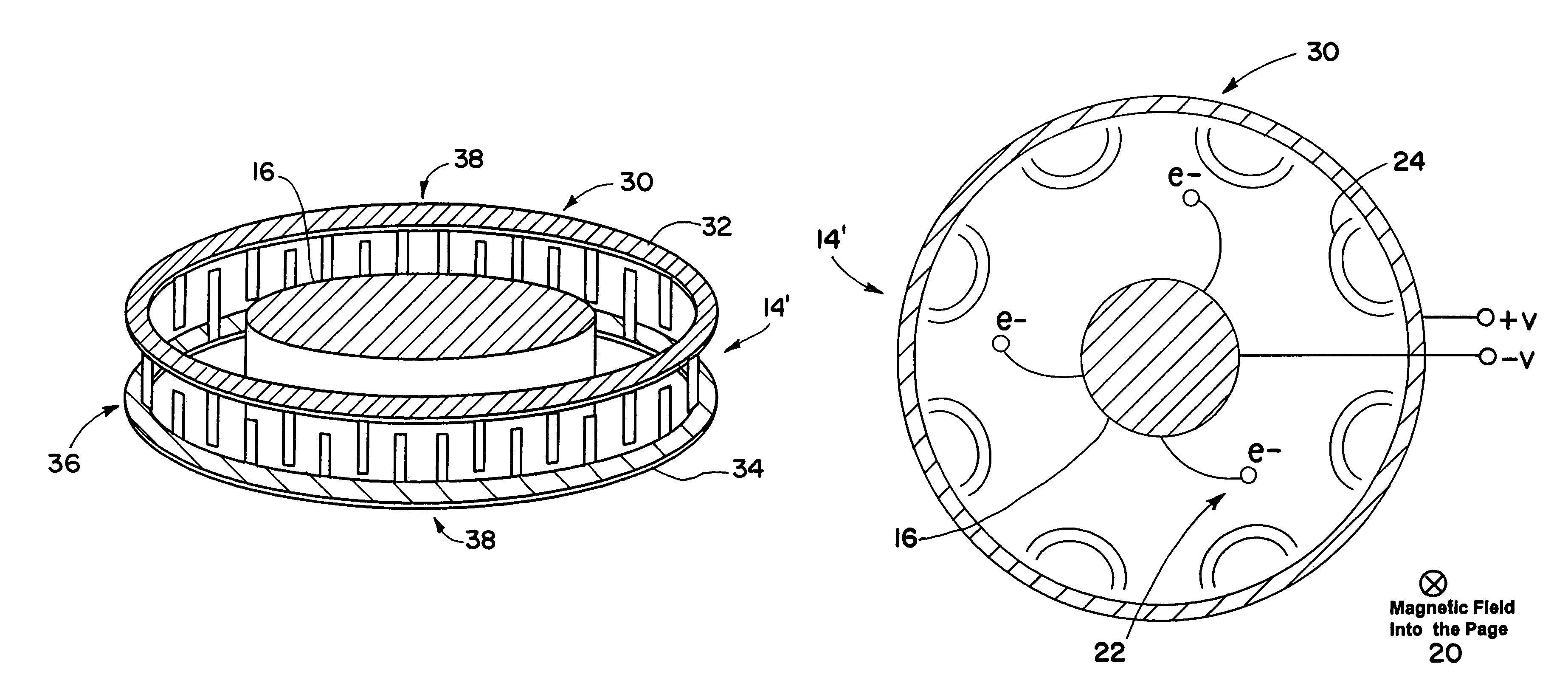
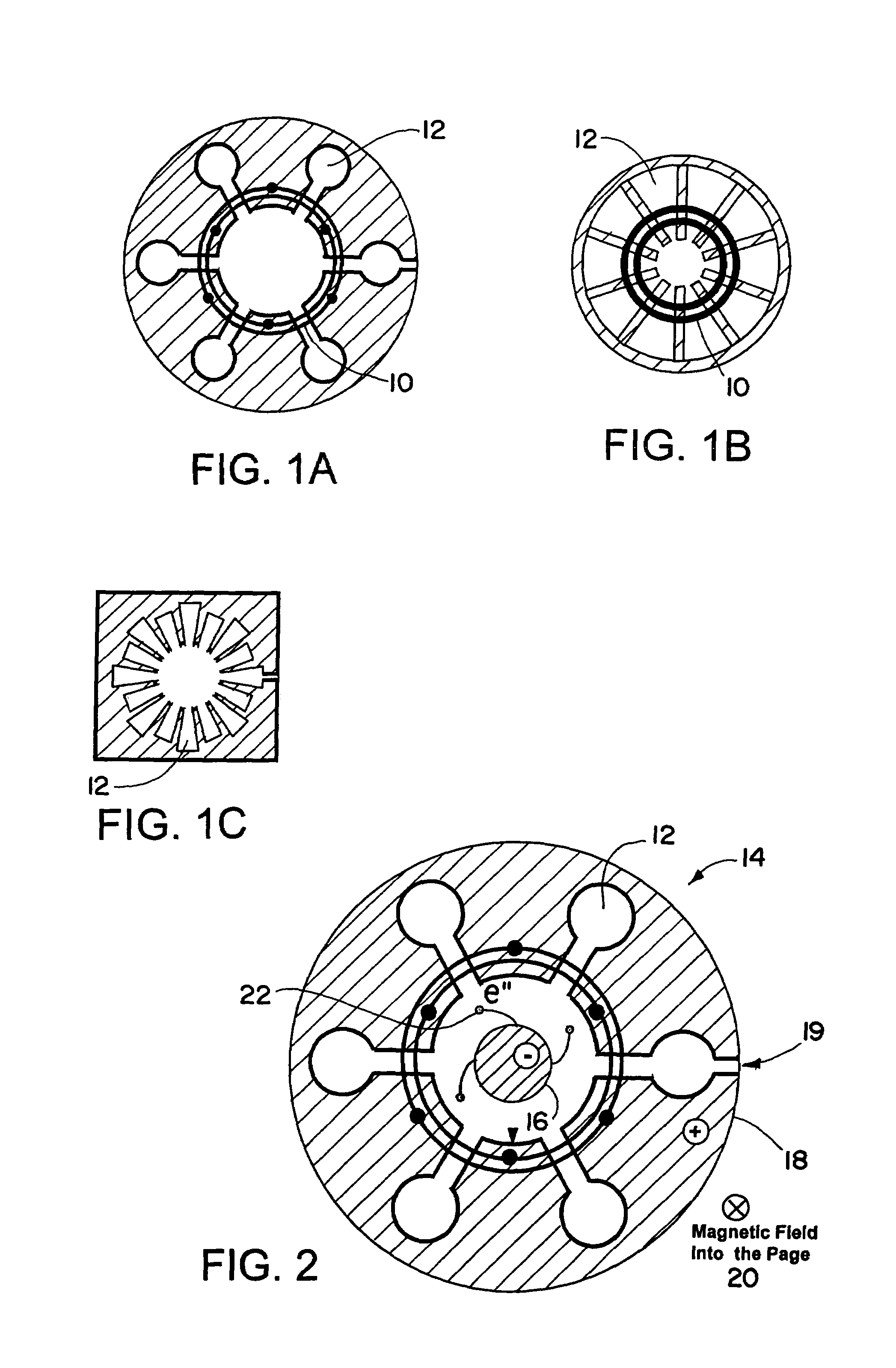
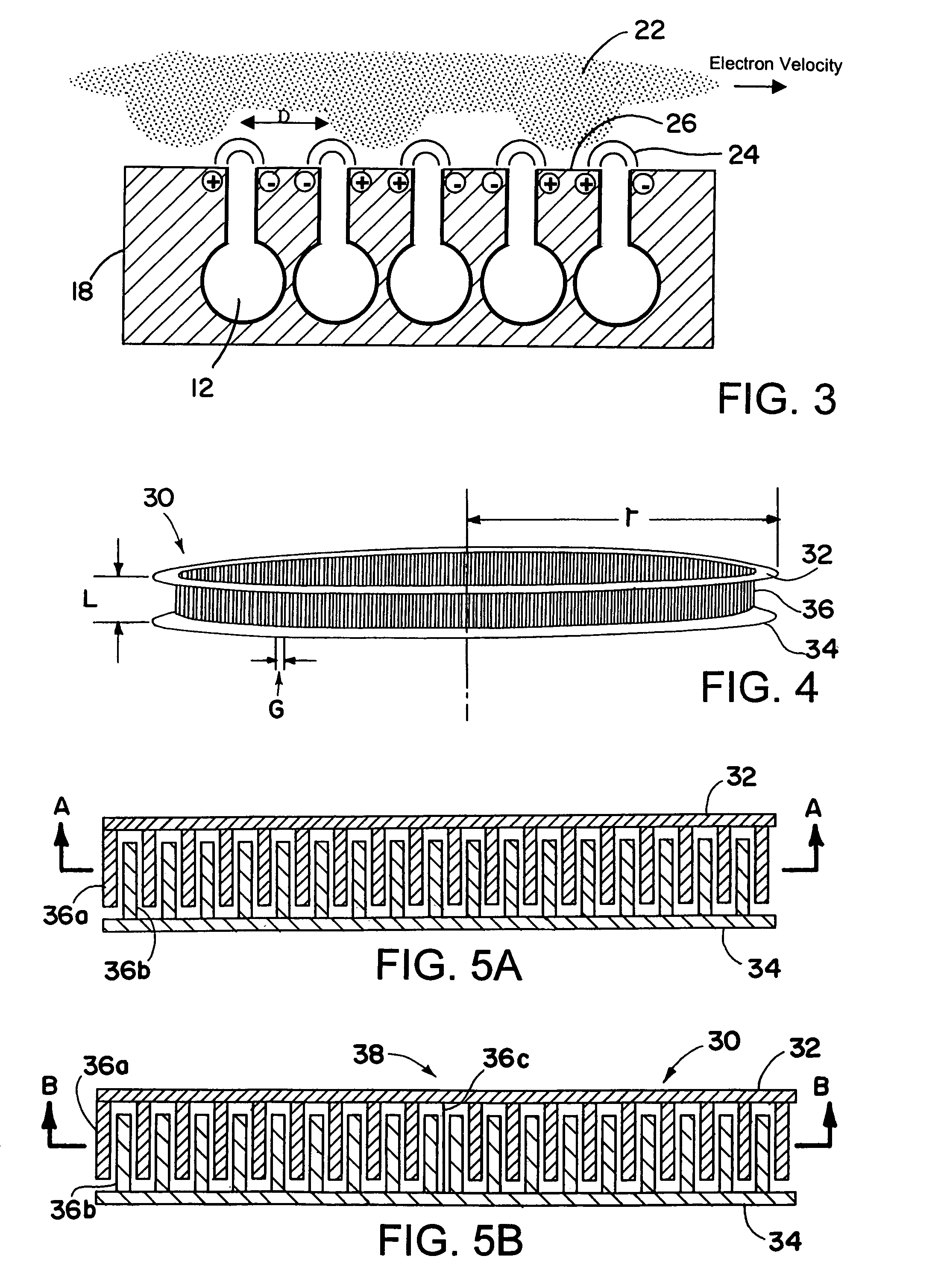
[0047]The applicants have discovered that large anodes, e.g., anodes with a circumference larger than one free-space wavelength, exhibit traveling waves along the inner circumference of the anode. In other words, the surface of the anode supports creeping waves that propagate around the circumference of the anode in both clockwise and counterclockwise directions. The traveling waves change phase as they travel around the anode and, at certain operating frequencies, look like standing waves, e.g., they are in phase with themselves as they complete one revolution around the anode. These stationary or standing modes perturb and control the phase of the individual resonators, thereby making pi-mode operat...


PUM


Abstract

An electromagnetic radiation source is disclosed. The electromagnetic radiation source includes an anode having a first conductor, a second conductor positioned relative to the first conductor, a plurality of pole pieces coupled to at least one of the first conductor and the second, and at least one mechanical phase reversal positioned along the first conductor or second conductor. Adjacent pole pieces are separated by a gap. The electromagnetic radiation source also includes a cathode separated from the anode by an anode-cathode space, electrical contacts for applying a dc voltage between the anode and the cathode and establishing an electric field across the anode-cathode space, and at least one magnet arranged to provide a dc magnetic field within the anode-cathode space generally normal to the electric field. Electrons emitted from the cathode are influenced by the electric and magnetic fields to follow a path through the anode-cathode space and pass in close proximity to the plurality of pole pieces, and the gaps between adjacent pole pieces provide fringing fields which interact with the electrons to produce single mode operation at a desired operating frequency.

Description

FIELD OF THE INVENTION[0001]The present invention relates generally to high frequency magnetrons and, more particularly, to magnetron anodes.BACKGROUND OF THE INVENTION[0002]Magnetrons are well known in the art and have long served as highly efficient sources of microwave energy. For example, magnetrons are commonly employed in microwave ovens to generate sufficient microwave energy for heating and cooking various foods. The use of magnetrons is desirable in that they operate with high efficiency, thus avoiding high costs associated with excess power consumption, heat dissipation, etc.[0003]Conventional microwave magnetrons employ a constant electric and magnetic field to produce a rotating electron space charge. The electron space charge interacts with a plurality of microwave resonant cavities to generate microwave radiation. Conventional magnetrons are efficient generators of microwave energy for frequencies in the 1 to 10 GHz region. At higher frequencies, the maximum output pow...

Claims


Application Information

Patent Timeline
Patent Type & Authority Patents(United States)
IPC IPC(8): G01J1/42H01J25/55
CPCH01J23/02H01J25/56
Inventor BAKER, C. VINCENTSMALL, JAMES G.
Owner RAYTHEON CO
Why Eureka
Try Eureka