System and method for phase-locked loop initialization

a phase-locked loop and initialization technology, applied in the field of initialization techniques of phase-locked loops, can solve the problems of inability to fully lock and initialize high-frequency pll circuits, inability to achieve lock and initialization for indeterminate periods of time, and failure to lock completely. to achieve the effect of facilitating initialization and reducing the time to lock

Inactive Publication Date: 2007-09-04
KK TOSHIBA
View PDF10 Cites 9 Cited by
  • Summary
  • Abstract
  • Description
  • Claims
  • Application Information

AI Technical Summary

Benefits of technology

[0009]A technical advantage of the invention is the ability to initialize the PLL circuit without adding circuitry to an input node of the voltage-controlled oscillator (VCO). The input node of a VCO is very sensitive to noise. Therefore, adding circuitry to the input node of a VCO may introduce jitter to the PLL circuit. Thus, the invention provides a method of initializing a PLL without adding noise to the input node of the VCO.
[0010]Another technical advantage of the invention is that improved PLL circuits such as those described herein may more quickly achieve lock. Because the PLL output frequencies are reduced to approach their minimum during a power on reset, the PLL does not have to work as hard to lock. Also, configuration bits may be advantageously set to values used exclusively for initialization in order to facilitate initialization. Therefore, the time to lock may be reduced. Further, the time to lock may be known. Because the status of the PLL circuit at each node may be known during or following the POR sequence, the time required for the PLL to achieve lock may be known, calculable, or at least more easily estimated. Thus, PLL applications having critical timing requirements may be improved with the PLL circuit configuration and / or initialization method described by this invention.
[0011]These, and other, aspects of the invention will be better appreciated and understood when considered in conjunction with the following description and the accompanying drawings. The following description, while indicating various embodiments of the invention and numerous specific details thereof, is given by way of illustration and not of limitation. Many substitutions, modifications, additions or rearrangements may be made within the scope of the invention, and the invention includes all such substitutions, modifications, additions or rearrangements.

Problems solved by technology

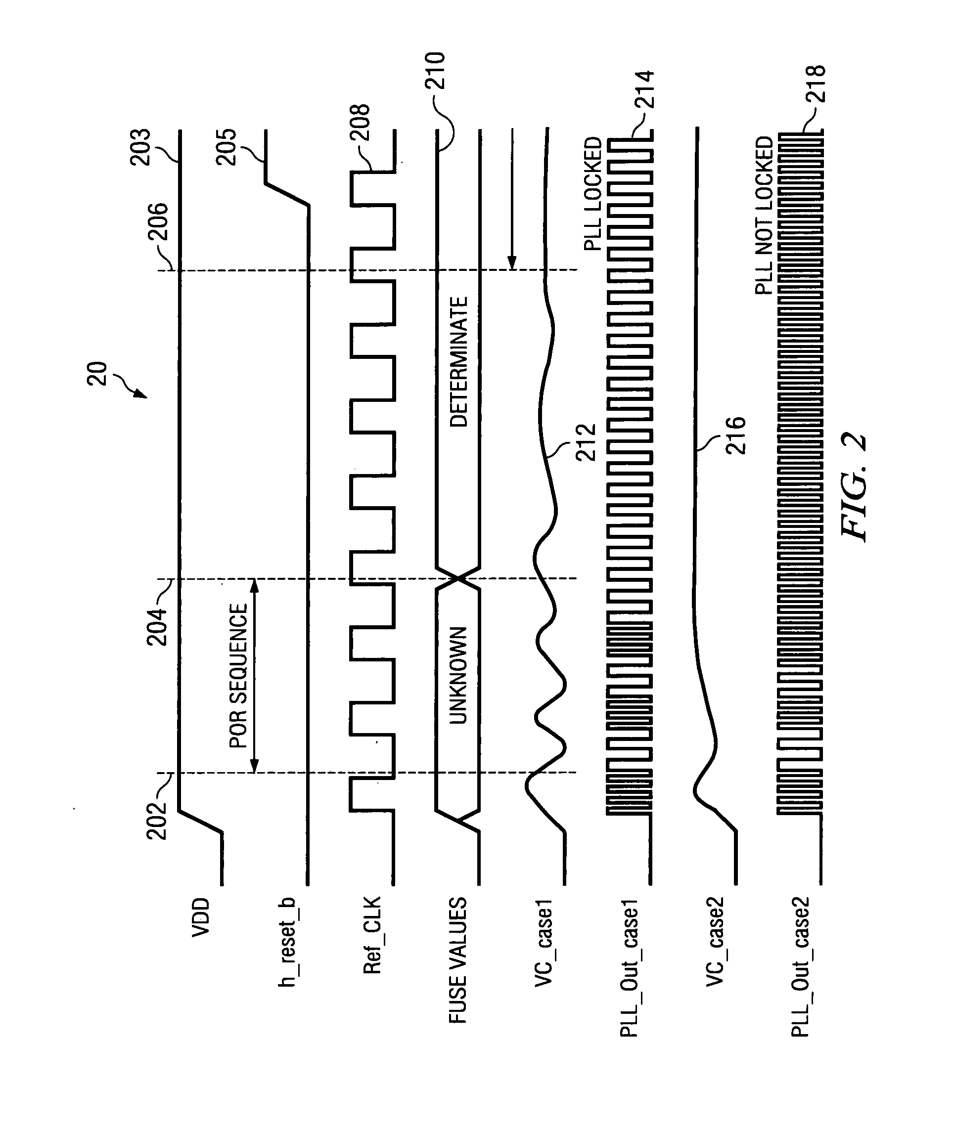
During a start-up process, high frequency PLL circuits may require indeterminate periods of time to achieve lock and initialize.
Some high-frequency PLL circuits may fail to lock entirely.
Thus, at start-up, some high-frequency PLL circuits may either lock after significant time and effort, or fail to lock entirely.

Method used


Image

  • System and method for phase-locked loop initialization
  • System and method for phase-locked loop initialization
  • System and method for phase-locked loop initialization

Examples


Embodiment Construction

[0020]The invention and the various features and advantageous details thereof are explained more fully with reference to the nonlimiting embodiments that are illustrated in the accompanying drawings and detailed in the following description. Descriptions of well known starting materials, processing techniques, components and equipment are omitted so as not to unnecessarily obscure the invention in detail. It should be understood, however, that the detailed description and the specific examples, while indicating preferred embodiments of the invention, are given by way of illustration only and not by way of limitation. After reading the specification, various substitutions, modifications, additions and rearrangements will become apparent to those skilled in the art from this disclosure which do not depart from the scope of the appended claims.

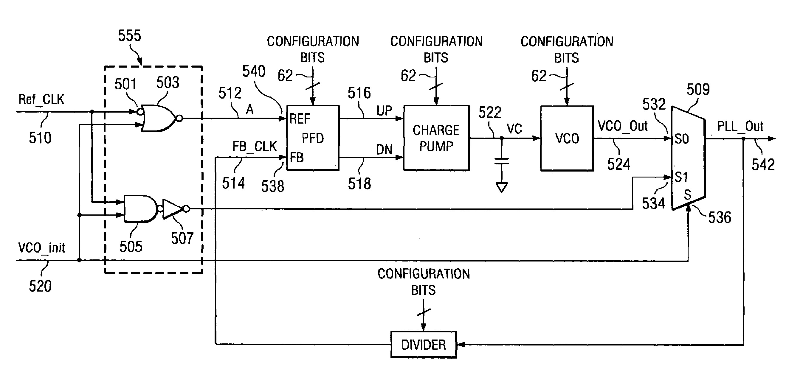
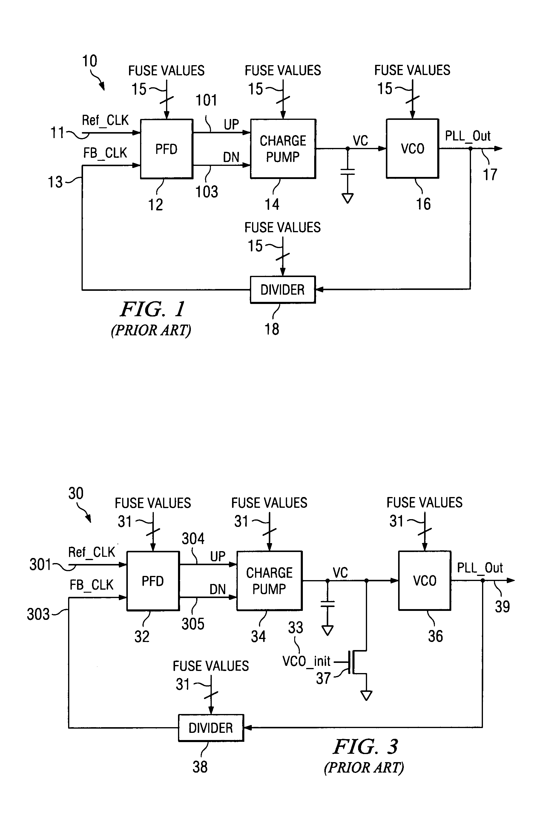
[0021]FIG. 1 is a block diagram of a typical phase-locked loop (PLL) circuit configured to receive fuse values 15. PLL 10 includes phase-frequen...


PUM


Abstract

Devices, methods, and systems for initializing a phased-lock loop (PLL) circuit which prevents or reduces the occurrences of voltage-controlled oscillator (VCO) frequency exceeding a divider's maximum input frequency, thus preventing or reducing at least one cause of lock failure. Disclosed is a PLL circuit having logic circuitry configured to hold a PFD reference-signal input low and provide a divided reference-signal to a PFD feedback-signal input while an initialization signal is asserted. The PLL can be initialized without adding circuitry to a VCO input. By asserting an initialization signal, an input voltage to a voltage-controlled oscillator is attenuated. The initialization signal is adapted to gate inputs to and outputs from the phase-locked loop circuit.

Description

TECHNICAL FIELD OF THE INVENTION[0001]The present invention relates to initialization techniques for a phase-locked loop (PLL) circuit, and more particularly, to initializing a PLL circuit during a power-on-reset sequence.BACKGROUND OF THE INVENTION[0002]Phase-locked loops are widely used in digital electronics, signal telemetry, and communications applications. Phase-locked loop (PLL) integrated circuits produce an oscillator frequency output which matches an input frequency signal. Many applications require phase-locked loop (PLL) circuits which will work with high frequencies. Some such applications utilize PLL circuits which are reconfigurable. During a start-up process, high frequency PLL circuits may require indeterminate periods of time to achieve lock and initialize. Some high-frequency PLL circuits may fail to lock entirely. In particular, some high-frequency PLL circuits may have voltage-controlled oscillators (VCOs) with maximum output frequencies which approach or exceed...

Claims


Application Information

Patent Timeline
Patent Type & Authority Patents(United States)
IPC IPC(8): H03L7/00
CPCH03L3/00H03L7/10Y10S331/02
Inventor MIKI, KAZUHIKO
Owner KK TOSHIBA
Why Eureka
Try Eureka