
Networks with sensors for air safety and security

a technology applied in the field of air safety and security networks, can solve the problems of difficult in situ measurement, difficult to measure the fluorescent characteristics of minuscule particles in airborne state, and sudden eruption of severe biological airborne perils at unpredictable locations, so as to improve the collection efficiency of impacting airborne particles and facilitate cleaning

Inactive Publication Date: 2007-09-04
FLIR DETECTION
View PDF68 Cites 27 Cited by
  • Summary
  • Abstract
  • Description
  • Claims
  • Application Information

AI Technical Summary

Benefits of technology

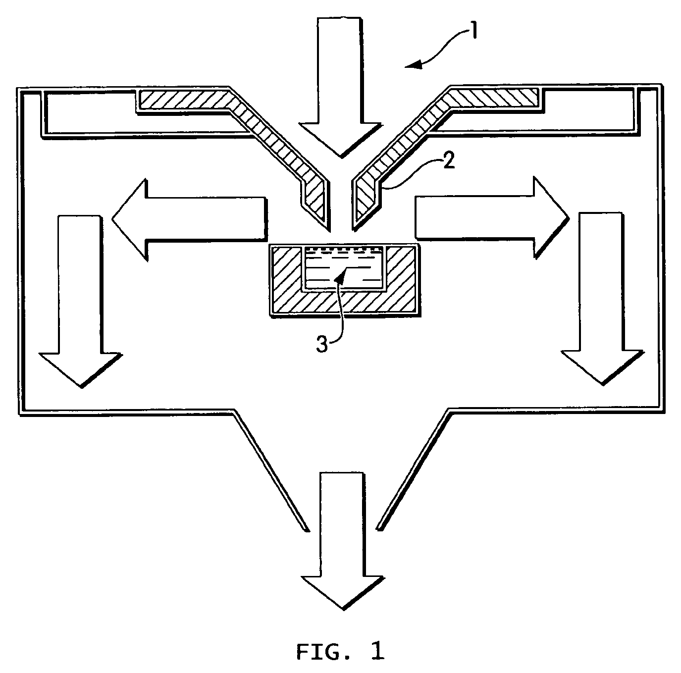
"The present invention relates to methods and devices for continuously monitoring airborne particles. The methods involve depositing airborne particles on a collection surface and analyzing them using various techniques such as impaction, collection, and pre-treatment steps. The devices include an impaction plate with a smooth collection surface and a spotting nozzle for directing an air stream towards the collection surface. The invention allows for the continuous monitoring of airborne particles, which can be useful in various applications such as biological, chemical, or radiological hazard monitoring."

Problems solved by technology

Sometimes severe biological airborne perils may suddenly arise at unpredictable locations, such as in bio-terrorist attacks.
The typical problem facing the aerosol field is that of collecting and characterizing airborne particles.
While autofluorescent properties may be useful in detecting biological particles, their in situ measurement is challenging for a number of reasons.
It is particularly difficult to measure fluorescent characteristics of minuscule particles in an airborne state.
The particles are available for analysis quite briefly, thus making it difficult to determine several informative characteristics.
In addition, the equipment required comprises expensive powerful lasers and sensitive fluorescence photodetectors or photon counters.
The resulting devices are large and expensive, making this technology unlikely to be adopted for some applications, such as routine monitoring of civilian buildings.
Continuous use of consumables and / or labor can become problematical and prohibitively expensive.
Therefore, monitoring systems based on extractive techniques are also of questionable value for routine, continuous use.

Method used


Image

  • Networks with sensors for air safety and security
  • Networks with sensors for air safety and security
  • Networks with sensors for air safety and security

Examples


example

Detection of Aerosolized Fluorescent Particles Using a Regenerative Surface

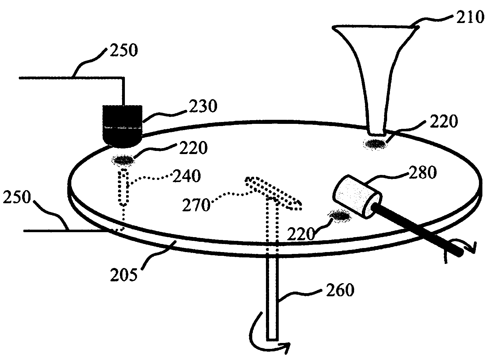
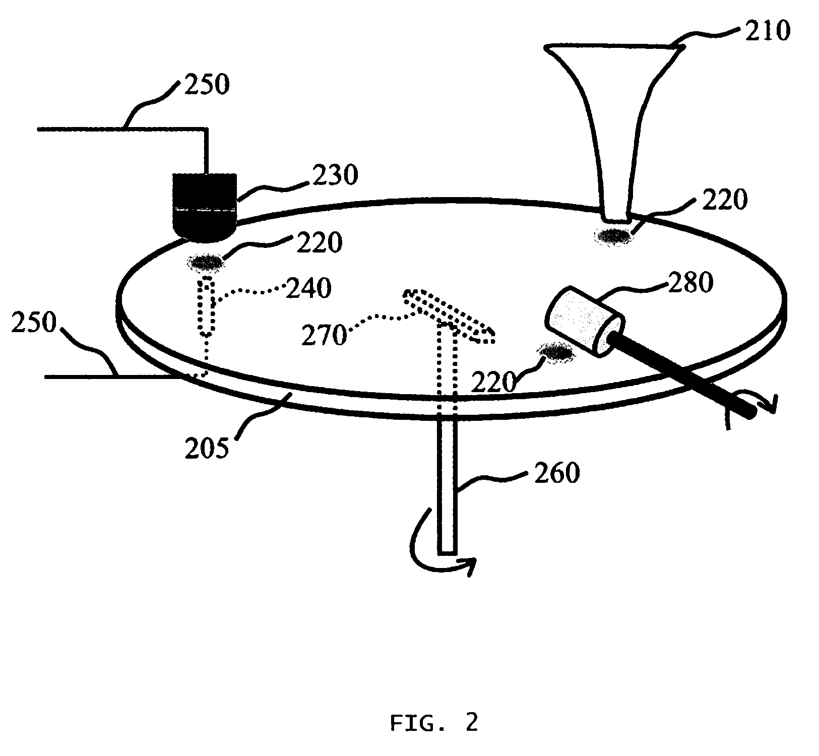
[0146]A regenerative surface air sampler based was constructed. The impaction plate was made of aluminum, and was shaped as a lobed cam with three regenerative surfaces. Components of the system included an inertial impactor, a fluorescence detector, and a felt wheel brush surface regenerator. The fluorescence detector was arranged essentially as depicted in FIG. 5, with transmission characteristics of the dichroic mirror, excitation and emission filters as shown in FIG. 7. The UV LED emission was specified to be about 375+ / −3 nm.

[0147]Biological aerosol was simulated with a fluorescent powder (UVPN UV Powder sold by LDP, LLC (www.maxmax.com)). It was aerosolized by tapping an open envelope of the powder three times, releasing approximately 100 milligrams of the powder into the air several feet away from the air inlet to the sensor.

[0148]Results of the test are shown in FIG. 8. As can be seen, the apparatus r...


PUM

PropertyMeasurementUnit
sizeaaaaaaaaaa
sizesaaaaaaaaaa
volumeaaaaaaaaaa

Abstract

Airborne particles are impacted on a collection surface, analyzed, and then the collection surface is regenerated. Thus, the same collection surface can be used in numerous cycles. The analysis can be focused on one or more properties of interest, such as the concentration of airborne biologicals. Sensors based on regenerative collection surfaces may be incorporated in many networks for applications such as building automation.

Description

FIELD OF INVENTION[0001]The invention relates to methods and devices for continuous monitoring of airborne particles, airborne biological particles, and systems of monitoring air quality.BACKGROUND OF INVENTION[0002]Monitoring airborne particles is of concern in a number of civilian and military contexts. Airborne hazards can come in a variety of forms, for example, of biological, chemical, or radiological nature. Sometimes severe biological airborne perils may suddenly arise at unpredictable locations, such as in bio-terrorist attacks. The most efficient response to biohazards can be mounted based on their earliest practicable detection.[0003]The typical problem facing the aerosol field is that of collecting and characterizing airborne particles. Characterization of these airborne particles can be performed in situ (i.e., while the particles remain suspended in a gas), or in extractive techniques where particles are collected and then deposited onto a solid substrate or into a liqu...

Claims


Application Information

Patent Timeline
Patent Type & Authority Patents(United States)
IPC IPC(8): G08B1/08G01N1/02G01N1/22G01N1/28G01N15/00G01N15/02G08B21/12
CPCG01N1/2208G01N15/0255G08B21/12G08B31/00G01N2001/022G01N2001/2223G01N2001/2276G01N2001/2833G01N2015/0088G01N2015/0261G01N2015/019
Inventor CALL, CHARLES JOHNBECKIUS, ROBERTMERRILL, EZRA
Owner FLIR DETECTION
Learn More