Booster with reduced dead travel and a braking system comprising such a booster

a technology of dead travel and braking system, which is applied in the direction of fluid coupling, rotary clutch, servomotor, etc., can solve the problem of extremely complex structure of the device and achieve the effect of convenient adaptation

Inactive Publication Date: 2007-09-11
ROBERT BOSCH GMBH
View PDF8 Cites 5 Cited by
  • Summary
  • Abstract
  • Description
  • Claims
  • Application Information

AI Technical Summary

Benefits of technology

[0008]It is consequently an object of the present invention to provide a braking device with sh

Problems solved by technology

The device is thus structurally extremely complex since it requires contorting

Method used


Image

  • Booster with reduced dead travel and a braking system comprising such a booster
  • Booster with reduced dead travel and a braking system comprising such a booster
  • Booster with reduced dead travel and a braking system comprising such a booster

Examples


second embodiment

[0100]FIGS. 7, 7a, 8, 9, 9a and 10 show a booster according to a We will focus on describing only the central part of the booster, that is to say the three-way valve and reaction devices, the other components being of more or less the same structure as those described in FIGS. 1 to 7.

[0101]The pneumatic piston 12 is traversed by the axial bore 34, in which the bushing 54 is slideably mounted in a sealed manner; in particular, the bushing comprises a first larger-diameter rear axial portion 160 slideably mounted in the second part 38 of the bore 34 and a second smaller-diameter front portion 162 slideably mounted in the third part 40 of the bore 34. The first portion 160 and the second portion 162 are connected by a shoulder 164.

[0102]The O-ring seal 66 providing sealing for the sliding movement of the bushing in the bore 34 is mounted in a groove in the rear portion 160 of the bushing.

[0103]The first key 84 is mounted fixedly on the bushing 54 according to the second embodiment, pa...

first embodiment

[0104]The second key is identical to the key described above for the

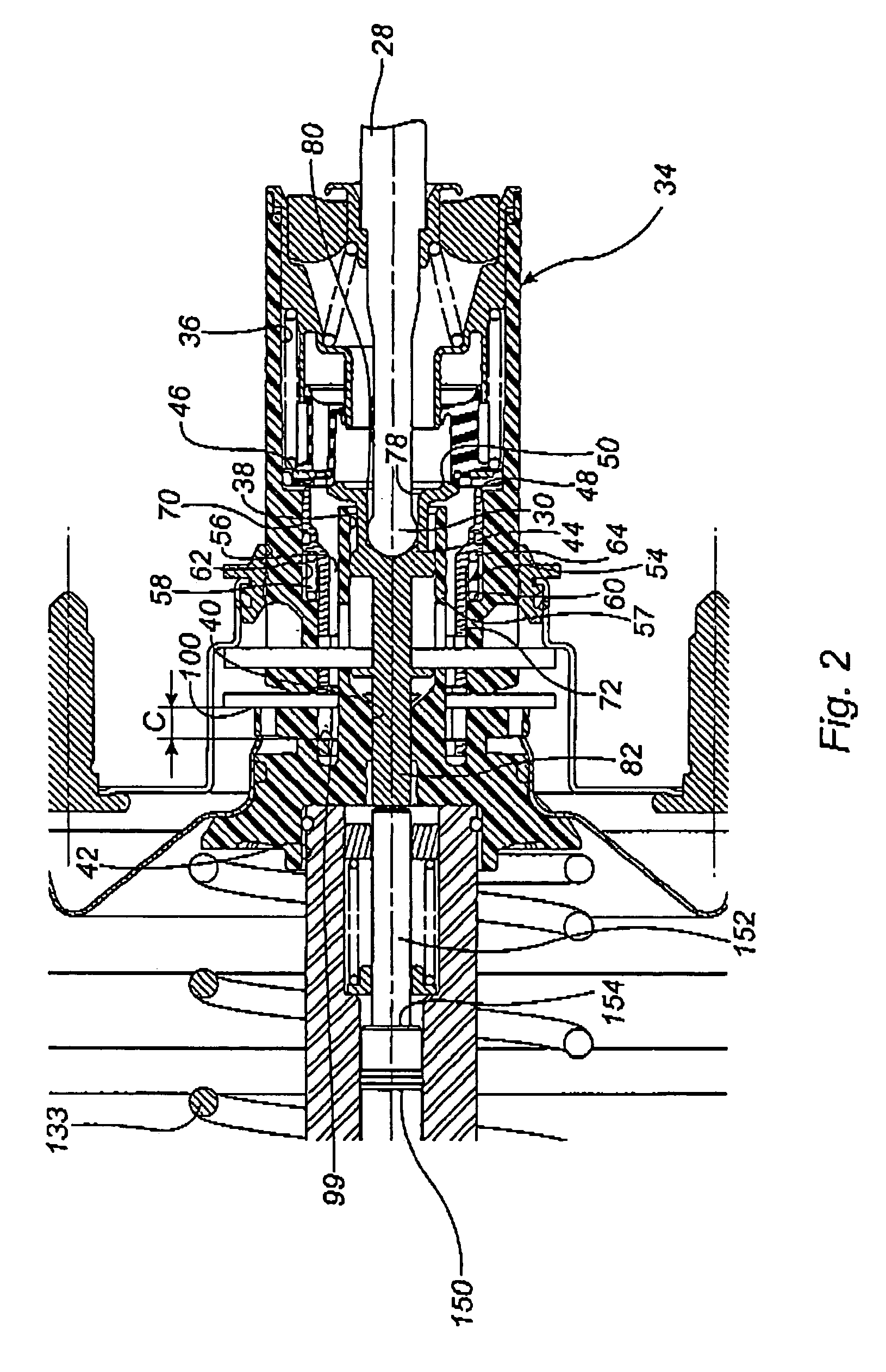
[0105]The elastic means 58 keeps the bushing immobile with respect to the piston 12 until such time as the piston 12 has completed the travel C, that is to say until such time as the rear ends 99′ of the first apertures have come into contact with the rear face 100′ of the first key 84. The elastic means bears by way of a first longitudinal rear end 174 against a front shoulder 170 made on the outer wall of the bushing and by way of a second longitudinal front end 176 against an annular narrowing 172 at the front end of the third part 40 of the bore 34. Advantageously, the annular narrowing 172 extends axially rearward by way of a cylindrical portion forming a transverse retaining stop for the front end 176 of the elastic means 58. The elastic means is advantageously a cylindrical spring.

[0106]The return spring 112 for the control rod 28 is mounted so that it bears between a rear end of the bushing 54 and the contro...


PUM


Abstract

A pneumatic brake booster with short actuating travel, comprising a skirt and a pneumatic piston that are rigidly connected and slideably mounted in a sealed casing to delimit a low-pressure chamber and a variable-pressure chamber and a three-way valve arrangement that is controlled by a control rod connected at a first end to a brake pedal. The three-way valve arrangement having first and second valve seats and a valve that is applied to at least one of the first and second valve seats by a valve spring. The second valve seat being borne by a first longitudinal end of a plunger distributor while the first valve seat is borne by a first longitudinal end of a bushing slideably mounted in a sealed manner in the pneumatic piston over a defined first travel and beyond the defined travel the bushing is secured axially to the pneumatic piston.

Description

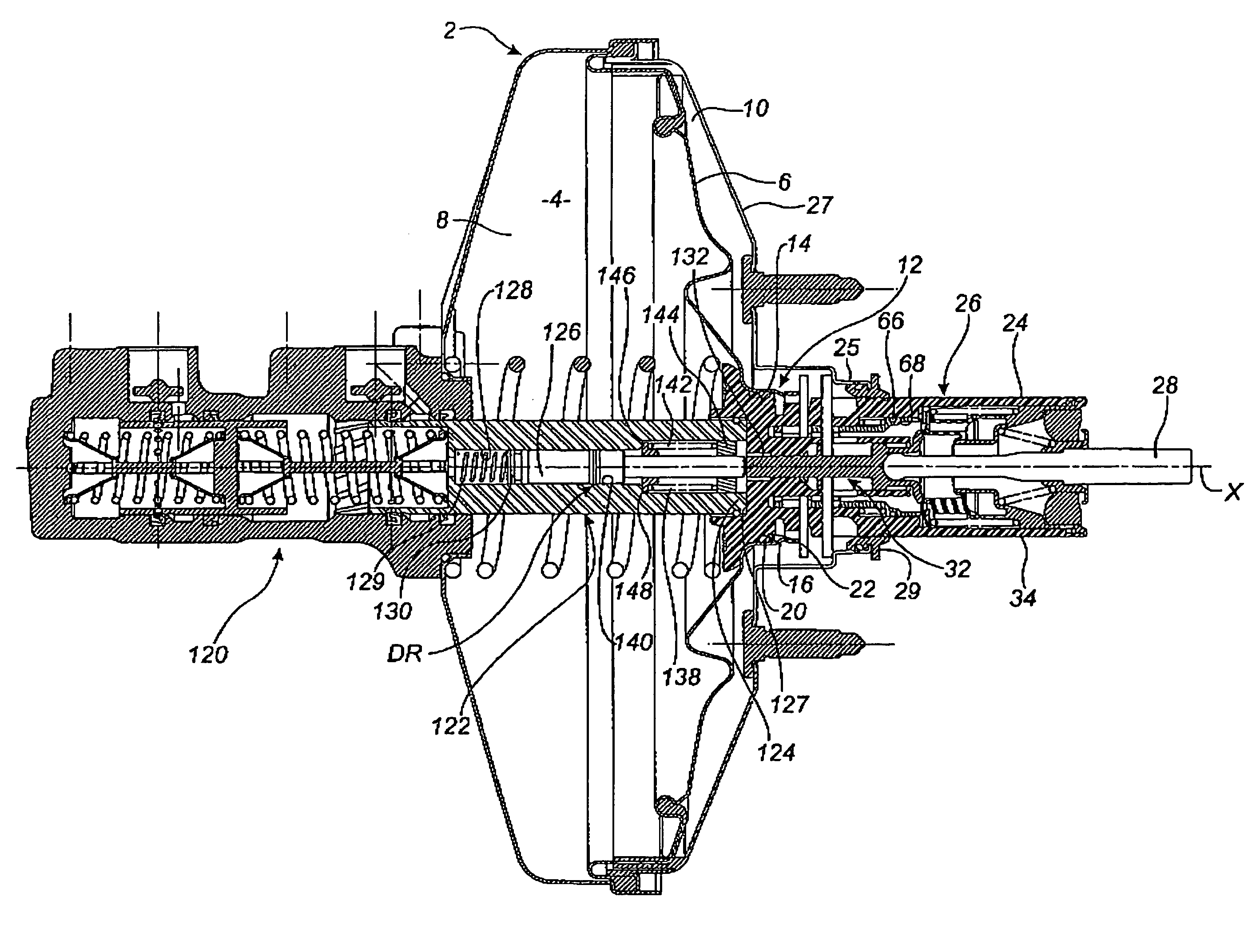
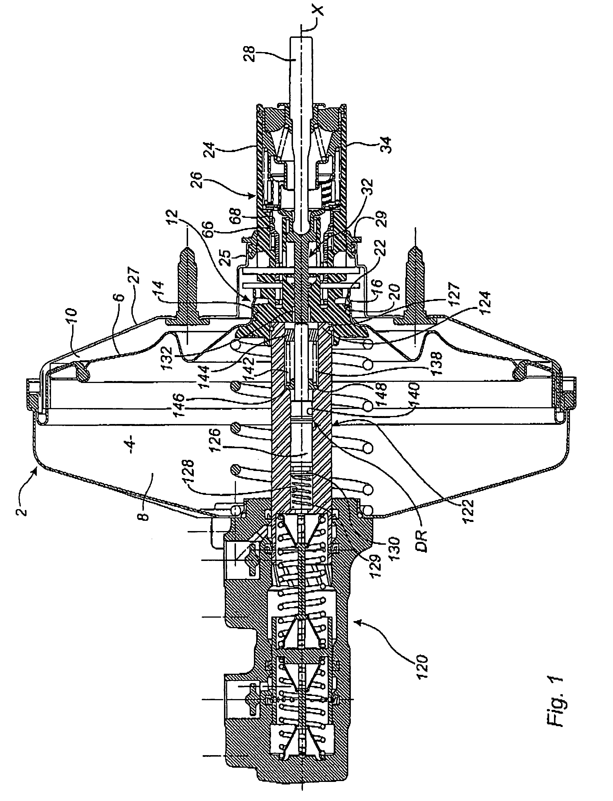
[0001]The present invention relates primarily to a rapid-actuation pneumatic brake booster and to a braking system comprising such a booster.BACKGROUND OF THE INVENTION[0002]A rapid-actuation braking device, also referred to as a reduced dead travel braking device, is known from the prior art and comprises a master cylinder actuated by a control rod actuated by a driver, the action of the driver being amplified by a pneumatic booster by means of which it is possible to reduce the pedal travel necessary to obtain a braking action.[0003]The booster of known type, described for example in document FR 2 696 143, comprises a casing in which a skirt dividing the inner space of the casing into a low-pressure chamber and a variable-pressure chamber is slideably mounted in a sealed manner.[0004]The skirt comprises a central passage in which is mounted a pneumatic piston provided with a three-way valve arrangement controlled by the control rod, placing the low-pressure chamber and the working...

Claims


Application Information

Patent Timeline
IPC IPC(8): F15B9/10B60T13/565B60T13/57B60T13/573
CPCB60T13/565B60T13/57B60T13/573
Inventor ATTARD, JEAN-MARCANDERSON, CHRISSPROCQ, RAYNALD
Owner ROBERT BOSCH GMBH
Why Eureka
Try Eureka