Signal transmission cable with adaptive contact pin reference

a transmission cable and contact pin technology, applied in the direction of cables, insulated conductors, coupling device connections, etc., can solve the problems of not being able to meet the needs of pivoting mechanisms, reducing the size of cable pivoting elements or fine conductor clusters, and large-size pivoting elements forming limits in the design of the main unit of the mobile phone. , to achieve the effect of high flexibility in us

Active Publication Date: 2007-09-11
ADVANCED FLEXIBLE CIRCUITS
View PDF4 Cites 29 Cited by
  • Summary
  • Abstract
  • Description
  • Claims
  • Application Information

AI Technical Summary

Benefits of technology

[0010]The signal transmission cable of the present invention may be applied to many electronic apparatus having a one-dimensional or a two-dimensional pivoting mechanism provided thereon, and has adaptive contact pin reference that can be adjusted to adapt to the electronic element to be connected to two ends of the cable. Therefore, the signal transmission cable of the present invention is highly flexible in use without being limited by the contact pins thereof.

Problems solved by technology

While the conventional cable works well when being used between two fixed connecting elements, it could not be satisfactorily used with pivoting mechanisms.
While the miniaturized cable and the cluster of very fine conductors may be used as an alternative for transmitting signals via the mobile phone, they do not permit the pivoting elements for the cable or the cluster of fine conductors to be reduced in size.
In other words, the large-size pivoting elements would form a limit in designing the main unit of the mobile phone.
And, the conventional cable no longer meets these requirements.
When the conventional cable is used with the existing size-reduced pivoting mechanism, it would adversely affect the operation of the pivoting mechanism.
In a worse condition, some of the conductors in the cable would become damaged.
While the clustered cable can be successfully extended through the hole on a pivot element, there is still a big problem in designing the contact pins at two ends of the cable for connecting to electronic components, such as connectors or soldering points.
When the contact pins on the cable and the circuit substrate are different from one another, problems would occur in the connection operation.
These cables with different contact pins not only increase the R&D and manufacturing costs, but also bring confusions to users.

Method used


Image

  • Signal transmission cable with adaptive contact pin reference
  • Signal transmission cable with adaptive contact pin reference
  • Signal transmission cable with adaptive contact pin reference

Examples


Embodiment Construction

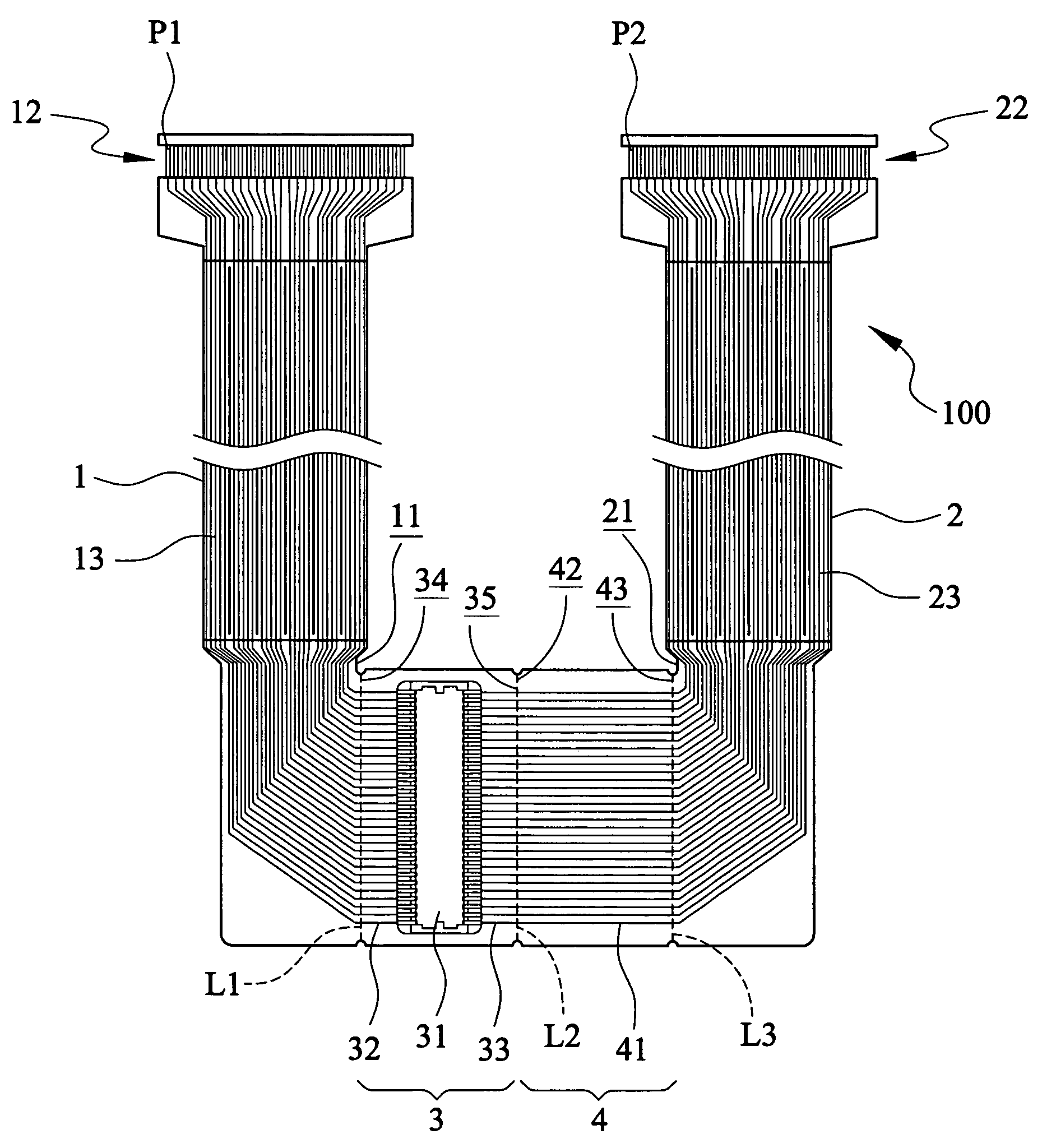
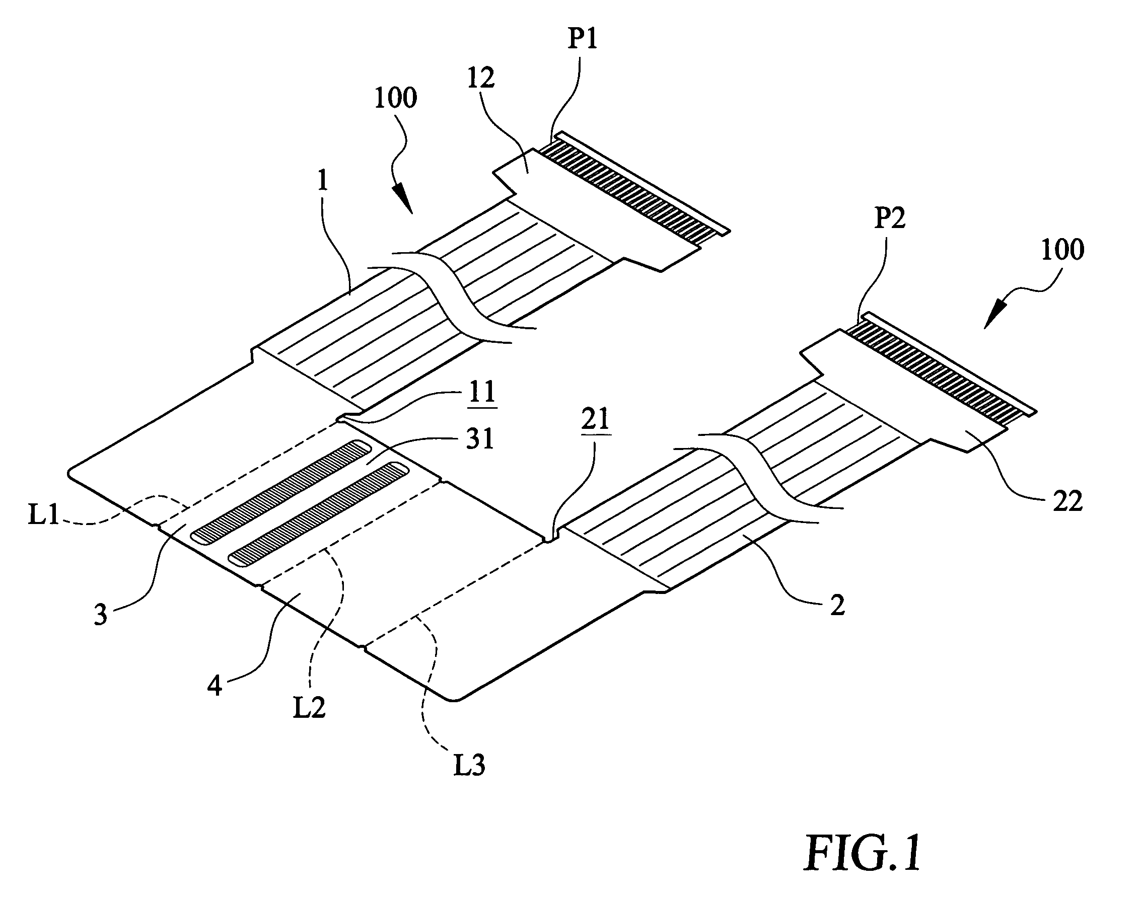
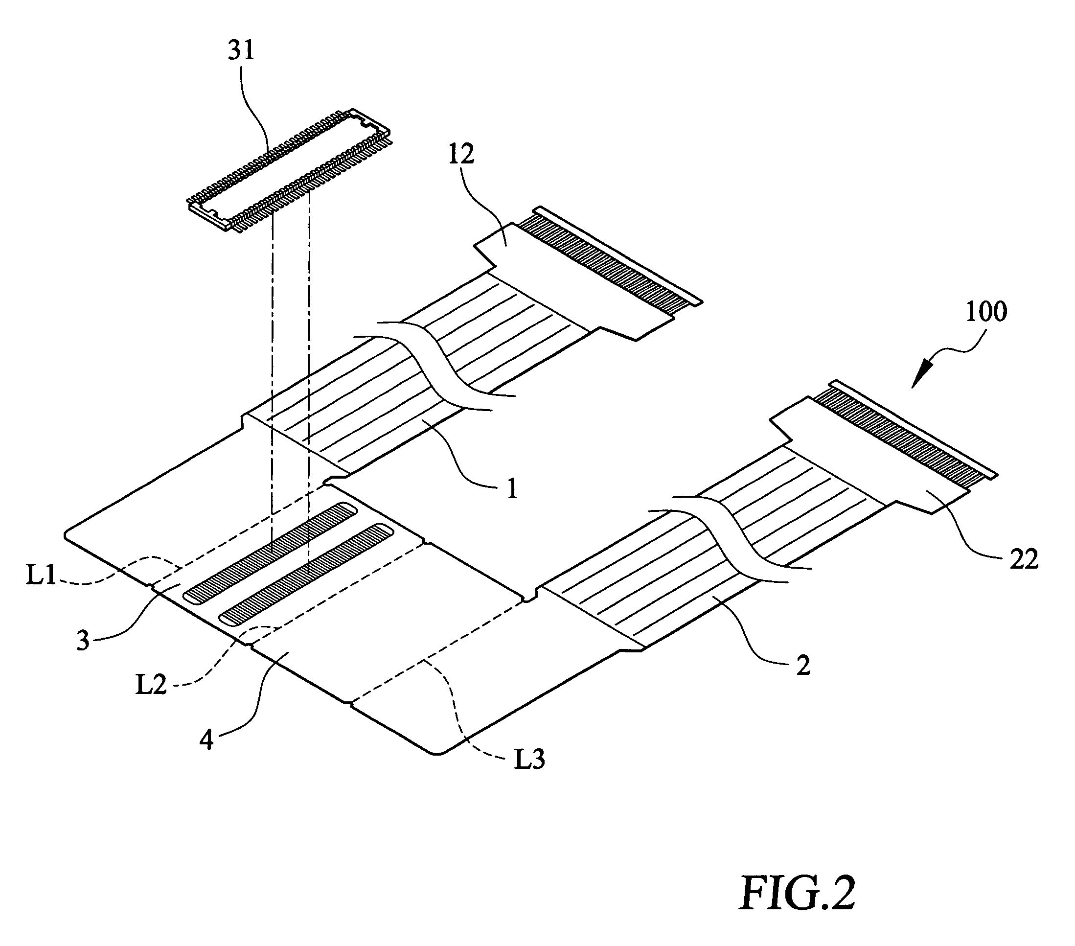
[0026]Please refer to FIGS. 1, 2, and 3 that are developed perspective view, developed exploded perspective view, and developed plan view, respectively, of a signal transmission cable with adaptive contact pin reference 100 according to a first embodiment of the present invention.

[0027]As shown, the signal transmission cable 100 is produced using the soft circuit board technique, and includes two parallelly extended cables, namely, a first cable 1 and a second cable 2.

[0028]The first cable 1 has a connecting edge 11 and a plug terminal 12, and includes a plurality of signal transmission lines 13, as shown in FIG. 3. The plug terminal 12 may be a conventional golden finger plug terminal or a plug terminal with a relief contact section. The plug terminal 12 has a plurality of pins, and each of the pins has a predetermined number, such as pin 1 to pin 60. One of the pins is a first reference pin P1 used as identification.

[0029]The second cable 2 has a connecting edge 21 and a plug term...


PUM


Abstract

A signal transmission cable with adaptive contact pin reference structure includes a first cable having a connecting edge; a second cable having a connecting edge; a component lay-out section having a first lateral edge adjacent to the connecting edge of the first cable, and a second lateral edge; and an overlapping section having an inner lateral edge adjacent to the second lateral edge of said component lay-out section with a folding line formed between them, and an outer lateral edge adjacent to the connecting edge of the second cable with another folding line formed between them. Signal transmission lines included in the component lay-out section and the first cable are correspondingly connected with one another, and signal transmission lines included in the overlapping section are correspondingly connected to those included in the second cable and the component lay-out section.

Description

FIELD OF THE INVENTION[0001]The present invention relates to a signal transmission cable, and more particularly to a signal transmission cable with adaptive contact pin reference.BACKGROUND OF THE INVENTION[0002]A conventional cable includes a plurality of parallelly arranged insulated conductors, and is used in various kinds of electrical appliances, electronic apparatus, computers, and communication apparatus to transmit signals. While the conventional cable works well when being used between two fixed connecting elements, it could not be satisfactorily used with pivoting mechanisms.[0003]However, pivoting mechanisms are often employed in many currently available electronic apparatus and communication apparatus. For example, the currently widely accepted mobile phones usually include a cover or a screen connected to a main unit of the mobile phone via a pivoting mechanism. At present, a miniaturized cable or a cluster of very fine conductors is used as a signal transmission cable ...

Claims


Application Information

Patent Timeline
Patent Type & Authority Patents(United States)
IPC IPC(8): H01R12/00
CPCH01R12/592H01R12/714H01R12/771H01R35/025H05K1/118H05K1/189H05K2201/055H05K2201/10189H05K2201/10356
Inventor LIN, GWUN-JINCHUO, CHIH-HENGSU, KUO-FU
Owner ADVANCED FLEXIBLE CIRCUITS
Why Eureka
Try Eureka