Locking ring for liner of acetabular cup

a technology of locking rings and acetabular cups, which is applied in the field of acetabular cups and locking rings, can solve the problems of increasing the possibility of failure of artificial hip joints, difficult, if not impossible, to remove locking rings, and inability to optimally form, so as to facilitate the insertion, easy to remove or expand, and easy to inser

Inactive Publication Date: 2007-09-11
ORTHOPEDIC SOURCE
View PDF12 Cites 37 Cited by
  • Summary
  • Abstract
  • Description
  • Claims
  • Application Information

AI Technical Summary

Benefits of technology

[0009]The locking ring has a break therein separating a captured end from a free end. The captured end is captured in some fashion to the first structure, such as the acetabular cup. This capturing means is preferably slidable, such as in the form of a post in the first structure residing within a slot in the captured end of the locking ring. The free end of the locking ring is adapted to be grasped so that the free end can be forced away from the captured end to expand a diameter of the locking ring. Such expansion moves the locking ring out of the seat and facilitates removal of the second structure, such as the liner, from the first structure, such as the acetabular cup. The locking ring can also accommodate snapping of the liner or other second structure easily into alignment mating with the first structure when the locking ring residing within the groove of the first structure snaps into the seat of the second structure.
[0010]Accordingly, a primary object of the prese

Problems solved by technology

The interior surface of the acetabular cup has this top bore and side holes passing therethrough, and so is not optimally formed to bear loads associated with the head of the artificial hip joint directly there against.
Such locking rings, while generally effective, can be difficult to insert, and typically once the liner has been secured within the acetabular cup, such locking rings are difficult, if not impossible, to remove, should it be desired by a surgeon to remove the liner after it has been placed within the acetabular cup with the locking ring.
Additionally, one particular problem with prior art acetabular cups and liners of artificial hip joints is that the top bore, unless plugged with an optional screw plug, provides a reg

Method used


Image

  • Locking ring for liner of acetabular cup
  • Locking ring for liner of acetabular cup
  • Locking ring for liner of acetabular cup

Examples


Embodiment Construction

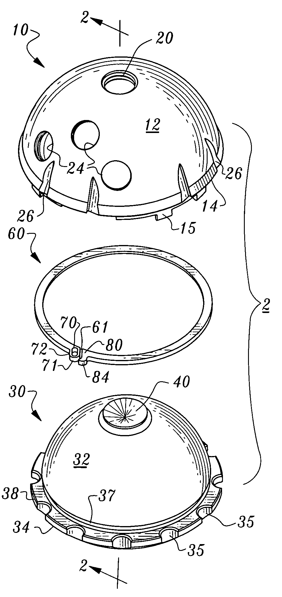
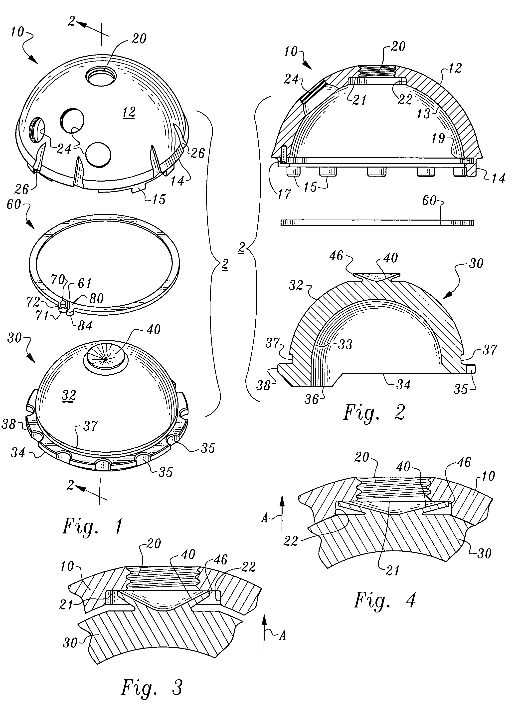
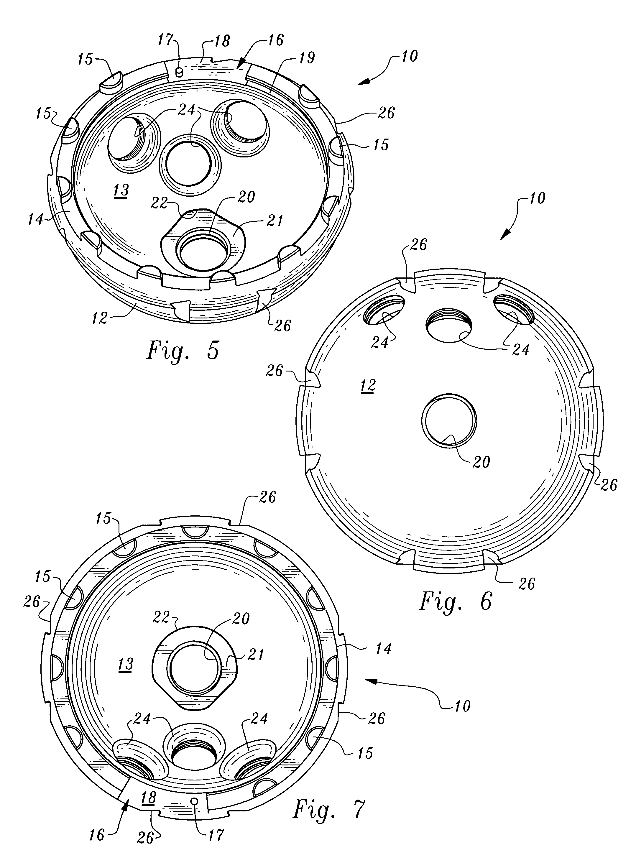
[0034]Referring to the drawings, wherein like reference numerals represent like parts throughout the various drawing figures, reference numeral 10 is directed to an acetabular cup (FIG. 1) adapted to receive a liner 30 therein for a portion of an artificial hip joint assembly 2 coupled to a hip bone. A locking ring 60 is provided to secure the liner 30 within the acetabular cup 10. With this artificial hip joint assembly 2 (FIGS. 1 and 2) a top bore 20 within the acetabular cup 10 is sealed by a top cone 40 of the liner 30 when the liner 30 is secured within the acetabular cup 10 by the locking ring 60. The locking ring 60 is easily positioned to hold the liner 30 within the acetabular cup 10 and easily enlarged to allow removal of the liner 30 from the acetabular cup 10.

[0035]In essence, and with particular reference to FIGS. 1 and 2, basic details of the artificial hip joint assembly 2 are described. The acetabular cup 10 is a generally hemispherical rigid structure having an exte...


PUM


Abstract

An artificial hip joint is provided including a generally hemispherical acetabular cup with a generally hemispherical liner mated within the acetabular cup and with a locking ring to secure the liner within the acetabular cup. The acetabular cup is adapted to be secured within a hip bone. The liner includes a hemispherical inside surface for pivotably supporting a head at an upper end of a femur. The locking ring resides within an annular groove in the acetabular cup and an annular seat in the liner. The locking ring includes a captured end and a free end. The captured end includes a slot which cooperates with a post in the acetabular cup to slidably hold the captured end to the acetabular cup. The locking ring removably attaches the liner to the acetabular cup.

Description

FIELD OF THE INVENTION[0001]The following invention relates to artificial hip joints, and particularly to acetabular cups thereof and the liners within the acetabular cups which rotatably support a head of the artificial hip joint supported by the femur. More particularly, this invention relates to locking rings for securely but removably holding the liner within the acetabular cup.BACKGROUND OF THE INVENTION[0002]Artificial hip joints have long been used to repair damaged hip joints and to restore maximum function to the hip joint. The hip bone includes an acetabulum in the form of a cup-shaped recess within the hip bone. The acetabulum receives a spherical head joined to an upper end of the femur through a neck. The head is rotatably supported within the acetabulum when the natural hip joint is functioning properly.[0003]In hip joint replacement surgery the acetabulum is appropriately modified to receive an acetabular cup therein. The acetabular cup is typically a rigid hemispheri...

Claims


Application Information

Patent Timeline
IPC IPC(8): A61F2/32
CPCA61F2/30721A61F2/34A61B17/86A61F2/30744A61F2/30771A61F2/4609A61F2002/30217A61F2002/30367A61F2002/30369A61F2002/30382A61F2002/30563A61F2002/30589A61F2002/30682A61F2002/3069A61F2002/30774A61F2002/30787A61F2002/3079A61F2002/30794A61F2002/30822A61F2002/3083A61F2002/325A61F2002/3291A61F2002/3401A61F2002/3404A61F2002/3414A61F2002/3433A61F2002/3443A61F2002/3451A61F2002/4629A61F2002/4641A61F2220/0033A61F2230/0067A61F2310/00017A61F2310/00023A61F2002/30331A61F2002/30495A61F2002/3054A61F2002/3241A61F2002/3403A61F2002/3429A61F2002/4631
Inventor MANDELL, STEVEN L.WILLIAMS, FREDRIC L.
Owner ORTHOPEDIC SOURCE
Why Eureka
Try Eureka