Determination of optical properties of a device under test in both directions in transmission and in reflection

a technology of optical properties and transmission, applied in the direction of optical apparatus testing, optical radiation measurement, instruments, etc., can solve the problems of not being able to measure pmd or pdl, and achieve the effect of little handling

Inactive Publication Date: 2007-09-11
KEYSIGHT TECH
View PDF8 Cites 0 Cited by
  • Summary
  • Abstract
  • Description
  • Claims
  • Application Information

AI Technical Summary

Benefits of technology

[0010]An advantage of the present invention is that the DUT can be characterized with as little handling as possible. This means that the DUT can be fully characterized to all parameters required when it is once connected to the measurement setup. i.e. without handling of the DUT all transmission and reflection parameters can be measured in both directions.
[0011]In an embodiment of the invention this can be realized by using a switch to direct the incoming light to one of the ports of the DUT. This allows full characterization of the DUT by two wavelength sweeps of the tunable laser source to measure all parameters required for both directions without handling the DUT.
[0012]In another embodiment of the invention the switch is replaced by a beam splitter to provide the DUT with the laser beam from both directions simultaneously. Here the two fractions of the light propagating through the DUT in opposite directions are coded by two modulation frequencies. Then, the signals are detected by using a phase sensitive detection scheme, i.e. by a frequency selective detection.
[0014]It is clear that the invention can be partly embodied or supported by one or more suitable software programs, which can be stored on or otherwise provided by any kind of data carrier, and which might be executed in or by any suitable data processing unit.

Problems solved by technology

However, with the disclosed measurement setup it is not possible to measure PMD or PDL.
Moreover, the measurement setup disclosed in this article causes problems because to enable the detectors used to detect the signals of reflection and transmission of both directions simultaneously, i.e. the reflected signal of one direction superimposed with the transmitted signal of the other direction and the transmitted signal of one direction superimposed with the reflected signal of the other direction, differences between the measurement and the reference path lengths are necessary to distinguish between these signals without really knowing all impacts of these differences.
Also the different path lengths for the various signals put additional requirements onto the receiver characteristics and the DUT characteristics which may be problematic for an accurate measurement.

Method used


Image

  • Determination of optical properties of a device under test in both directions in transmission and in reflection
  • Determination of optical properties of a device under test in both directions in transmission and in reflection
  • Determination of optical properties of a device under test in both directions in transmission and in reflection

Examples


Embodiment Construction

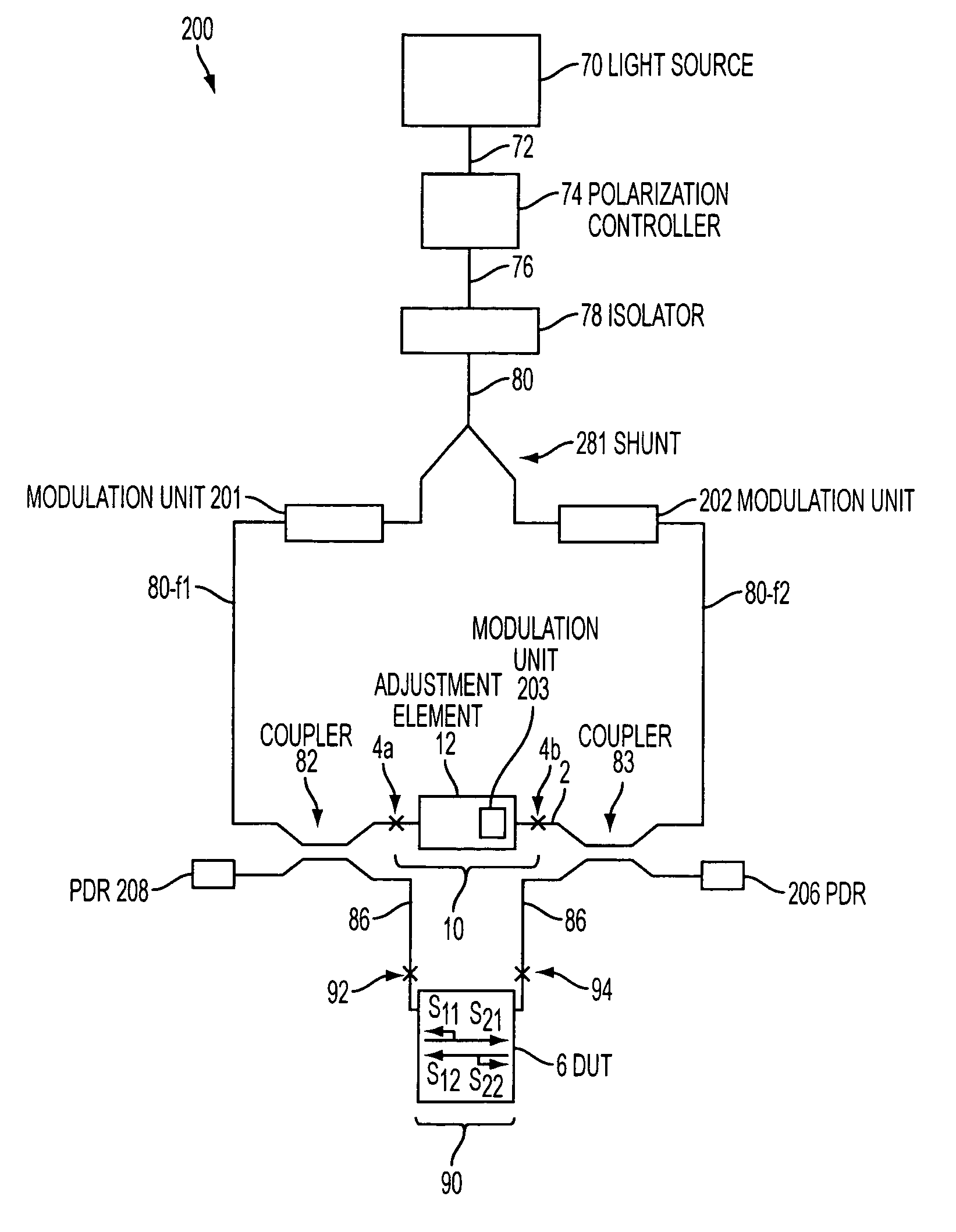
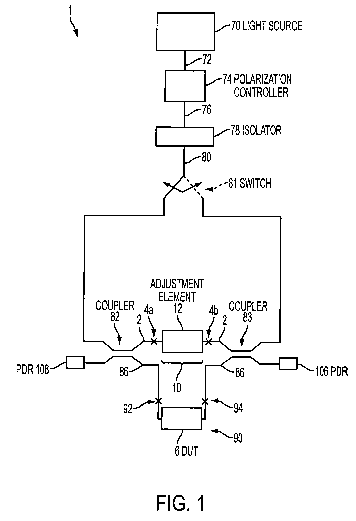
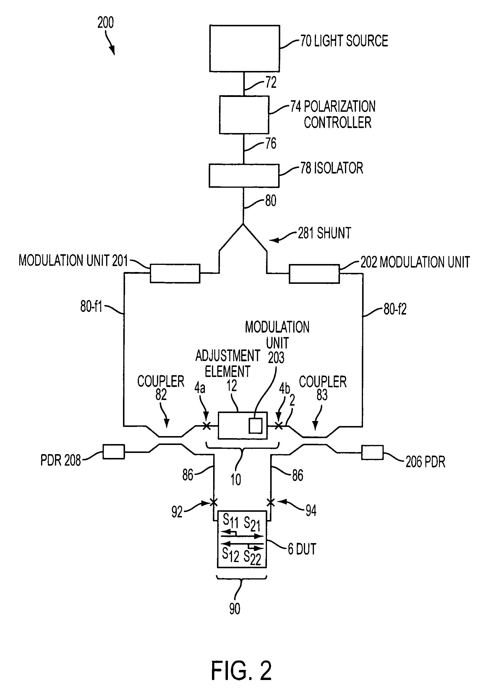
[0018]Referring now in greater detail to the drawings, FIG. 1 shows a first embodiment 1 of a measurement setup according to the present invention for determination of optical properties of a DUT 6 in transmission and in reflection in both directions.

[0019]Measurement setup 1 contains a tunable light source 70 which provides a coherent laser beam 72 to a polarization controller 74 (which can be a Hewlett-Packard HP 8169A). The polarization controller 74 provides a polarization controlled coherent light beam 76 to an isolator 78. Optically connected with the isolator 78 and receiving a coherent light beam 80 from the isolator 78 is a switch 81. The switch 81 is not located in the interferometric part of setup 1. Optically connected with the switch 81 is a first beam splitter 82 which is a 3 dB coupler. Also optically connected with the switch 81 is a second beam splitter 83 which is 3 dB coupler, also. Connected to both couplers 82 and 83 is a reference arm 2 and a measurement arm 86...


PUM

PropertyMeasurementUnit
transparentaaaaaaaaaa
optical propertiesaaaaaaaaaa
frequencyaaaaaaaaaa

Abstract

A method and a measurement setup for determination of optical properties of a device under test in both directions in transmission and in reflection, includes a coding device distinguishably coding at least two parts of a provided measurement signal, feeding elements feeding the at least two parts into the DUT from both directions, receiving elements receiving the signals from both directions transmitted and reflected by the DUT, identifying at least the coded parts in the signals transmitted and reflected by the DUT, and analyzing at least the identified parts to determine at least one optical property of the DUT from both directions in transmission and in reflection.

Description

[0001]This application is the National Stage of International Application No. PCT / EP02 / 00429, International Filing Date, 17 Jan. 2002, which designated the United States of America, and which international application was published under PCT Article 21(2) as WO Publication No. WO 03 / 060458 A1.BACKGROUND OF THE INVENTION[0002]The present invention relates to determination of optical properties, e.g. polarization dependent loss (PDL), polarization mode dispersion (PMD), differential group delay (DGD), insertion loss, return loss and / or chromatic dispersion (CD), of a device under test (DUT) in both directions in transmission and in reflection of an optical beam.[0003]Measurement setups for the above-mentioned purpose shall be as easy as possible to handle and shall reveal all optical properties of the DUT as fast as possible and with as little handling as possible. This means that the DUT should be fully characterized to all parameters required when it is once connected to the measure...

Claims


Application Information

Patent Timeline
Patent Type & Authority Patents(United States)
IPC IPC(8): G02F1/01H01J40/14G01M11/02G01M11/00
CPCG01M11/3181G01M11/33G01M11/331G01M11/39
Inventor ZIEGLER, PATRICKSTOLTE, RALFTHOMA, PETER
Owner KEYSIGHT TECH
Why Eureka
Try Eureka