Stator of rotary electric machine

a technology of rotary electric machines and stator cores, which is applied in the direction of magnets, winding head prevention/reduction, and magnets, etc., can solve the problems of likely increase in overcurrent loss due to leakage flux, and achieve the reduction of stator cores and coil end portions, reducing copper loss, and increasing efficiency

Inactive Publication Date: 2007-09-11
TOYOTA JIDOSHA KK
View PDF21 Cites 46 Cited by
  • Summary
  • Abstract
  • Description
  • Claims
  • Application Information

AI Technical Summary

Benefits of technology

[0020]With this structure, in the stator of a rotary electric machine (e.g., a synchronous motor) including a stator and a rotor, the stator includes the stator core having multiple slots; and the laminated flat-plate conductor (e.g., a laminated body coil) formed by laminating the predetermined number of flat-plate conductors (e.g., rolled copper material) each of which has a shape that opens such that the flat-plate conductor can be fitted to the stator core (e.g., a U-shape). The laminated flat-plate conductor can be fitted to the slots of the stator core so as to stride a tooth portion between the slots. After the laminated flat-plate conductor is fitted to the slots, the open end portion thereof is closed, whereby the coil is formed. Since such a laminated flat-plate conductor is formed, it is not necessary to obtain a space for winding, which corresponds to a size of the nozzle that is necessary when the coil is wound around the tooth directly by the nozzle. It is therefore possible to freely set the cross section of the laminated flat-plate conductor that is to be inserted into the slots. Namely, it is possible to set the cross section of the laminated flat-plate conductor such that the proportion of the cross sectional area of the laminated flat-plate conductor in the cross sectional area of the slot becomes high. Thus, a copper loss can be reduced. As a result, the efficiency can be increased. Further, the sizes of the stator core and the coil end portion can be reduced.
[0021]An over-current loss due to an over-current generated by leakage flux is likely to increase as the thickness of the flat-plate conductor through which an electric current flows increases. Therefore, in the laminated flat-plate conductor, by laminating multiple flat-plate conductors, an electric current is divided and flows in each turn of the flat-plate conductors constituting the laminated flat-plate conductor. Accordingly, an over-current loss can be reduced. Also, an electric power loss due to leakage flux can be reduced by reduction of an over-current loss. It is thus possible to provide a stator of a rotary electric machine in which the proportion of the cross sectional area of the coil in the cross sectional area of the slot is high, and an electric power loss due to leakage flux can be reduced.

Problems solved by technology

An over-current loss due to an over-current generated by leakage flux is likely to increase as the thickness of the flat-plate conductor through which an electric current flows increases.

Method used


Image

  • Stator of rotary electric machine
  • Stator of rotary electric machine
  • Stator of rotary electric machine

Examples


Embodiment Construction

[0045]Hereafter, a stator of a rotary electric machine according to an embodiment of the invention will be described with reference to accompanying drawings. In the following description, a stator of a synchronous motor is taken as an example. In the following description, the same reference numerals are assigned to the same elements. The names and functions of the elements having the same reference numerals are also the same. Therefore, concrete descriptions on the elements having the same reference numerals are made only once and not repeated.

[0046]Hereafter, a first embodiment will be described in detail.

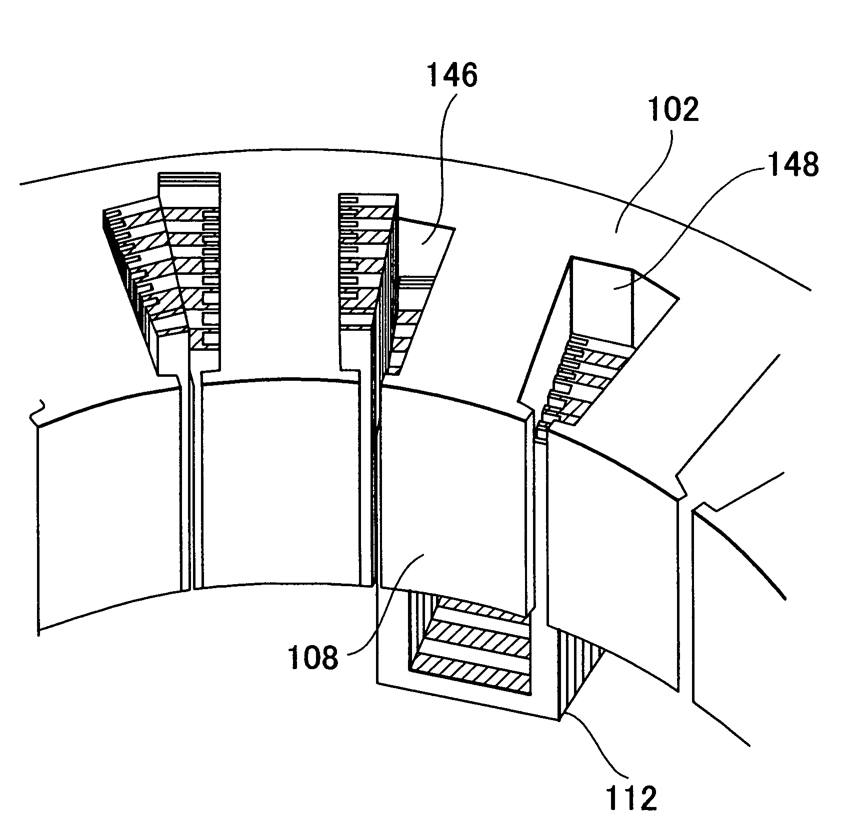
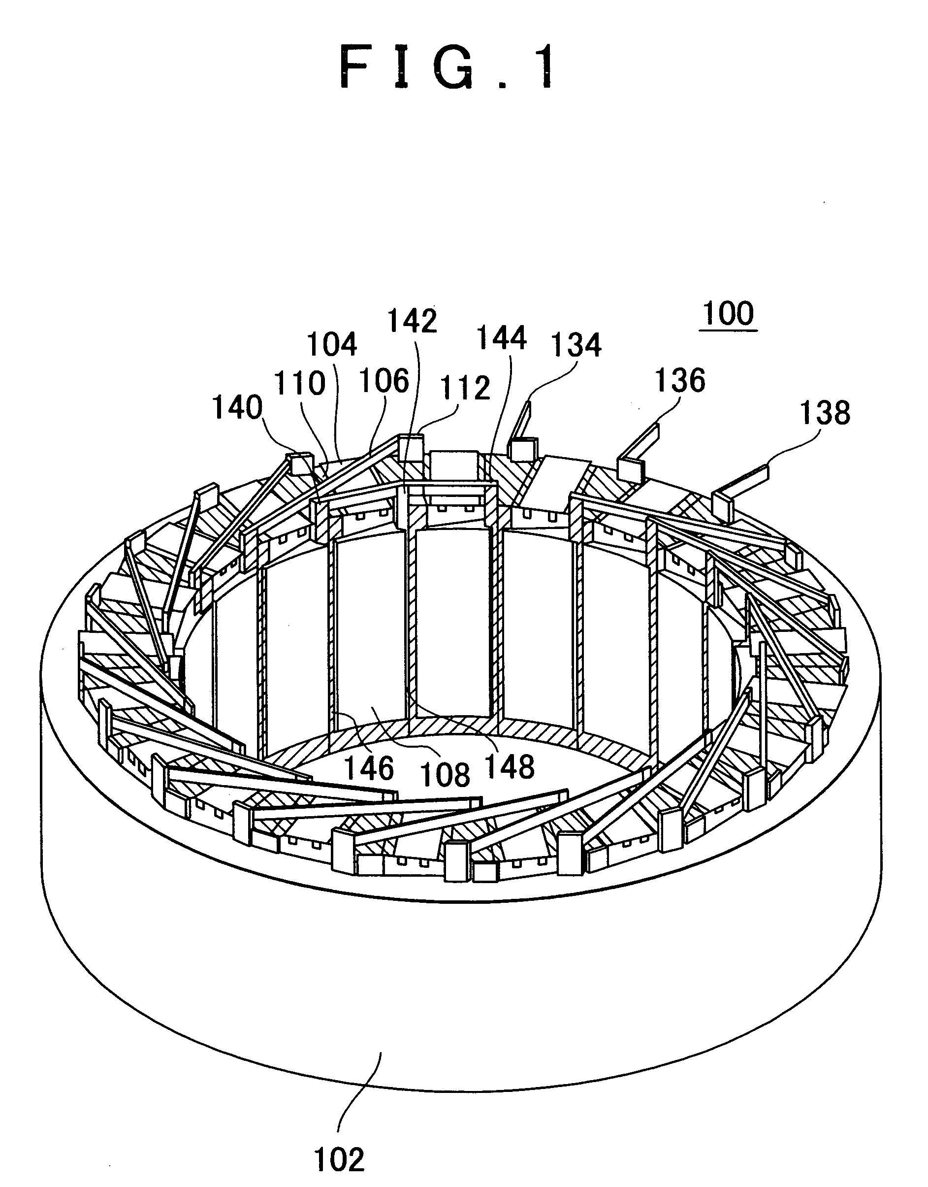
[0047]A stator according to the first embodiment is a stator of a synchronous motor provided with a stator and a rotor including a permanent magnet. As shown inFIG. 1, a stator 100 includes a stator core 102, a coil 112, a bus bar 110, a bus bar positioning block 104, and a crossover member 106.

[0048]The stator core 102 is formed by laminating multiple electromagnetic steel plate...


PUM

PropertyMeasurementUnit
widthaaaaaaaaaa
structureaaaaaaaaaa
areaaaaaaaaaaa

Abstract

There is provided a stator of a rotary electric machine in which the proportion of the cross sectional area of a coil in the cross sectional area of the slot is high, and an electric power loss due to leakage flux can be reduced. The stator is a stator of a rotary electric machine including a stator and a rotor. The stator includes a stator core having multiple slots in a direction parallel to a rotational axis of the rotary electric machine, and a laminated flat-body conductor which is formed, in a press process, by laminating a predetermined number of flat-body conductors each of which has a predetermined shape. According to the predetermined shape, the flat-plate conductor has an open end portion such that the flat-plate conductor can be fitted in the stator core. The laminated flat-body conductor is inserted in the slots of the stator core, and the open end portion of the laminated flat-plate conductor is closed, whereby a coil is formed.

Description

INCORPORATION BY REFERENCE[0001]The disclosure of Japanese Patent Application No. 2003-391181 filed on Nov. 20, 2003, including the specification, drawings and abstract is incorporated herein by reference in its entirety.BACKGROUND OF THE INVENTION[0002]1. Field of the Invention[0003]The invention relates to a structure of a rotary electric machine including a stator and a rotor. More particularly, the invention relates to a structure of a stator.[0004]2. Description of the Related Art[0005]Conventionally, as a stator of a rotary electric machine including a stator and a rotor (e.g., a synchronous motor), a stator of a rotary electric machine has been employed in which a nozzle is inserted into a slot, that is formed between teeth arranged in a stator core, from the inner peripheral side, that is, the side on which there is the axis of rotation of the synchronous motor, and a coil is wound around each of the teeth multiple times (this method is so-called nozzle direct winding). The ...

Claims


Application Information

Patent Timeline
Patent Type & Authority Patents(United States)
IPC IPC(8): H02K3/04H02K3/02H02K3/12H02K3/34H02K3/42H02K15/04
CPCH02K3/02H02K3/12H02K15/0414Y10T29/49009Y10T29/49073
Inventor HARADA, KENJIKATSU, TOSHIAKIMIZUTANI, RYOJI
Owner TOYOTA JIDOSHA KK
Why Eureka
Try Eureka