Inverter circuit for lighting discharge lamps with reduced power consumption

a technology of inverter circuit and discharge lamp, which is applied in the direction of climate sustainability, efficient power electronics conversion, and electric lighting sources, etc., can solve the problems of increasing the number of components, complicating the circuit structure, and failing to achieve favorable power efficiency, so as to facilitate the design of transformers.

Inactive Publication Date: 2006-06-27
MINEBEA CO LTD
View PDF6 Cites 6 Cited by
  • Summary
  • Abstract
  • Description
  • Claims
  • Application Information

AI Technical Summary

Benefits of technology

[0010]The present invention has been made in light of the above problems, and it is an object of the present invention to provide an inverter circuit for lighting discharge lamps, which is simply structured, enables stable operation of a circuit, and which has a further enhanced efficiency thereby reducing power consumption.
[0011]In order to achieve the object, according to one aspect of the present invention, an inverter circuit for lighting discharge lamps comprises: a transformer having a resonant circuit formed by a parasitic capacitance of a discharge lamp; an H-bridge circuit to drive a primary side of the transformer at a frequency which is less than a series resonant frequency of the resonant circuit, and at which phase difference in voltage and current at the primary side of the transformer falls within a predetermined range from its minimum; a logic circuit to generate, based on an output signal of an oscillating circuit, gate signals for driving the H-bridge circuit; and a step-up circuit to step up a DC supply voltage based on another output signal of the oscillating circuit, and to supply the logic circuit with the stepped up DC supply voltage as a supply voltage for generating the gate signals. Thus, the step-up circuit does not require an oscillating circuit dedicated thereto reducing the number of components, whereby the high withstand voltage FET of the H-bridge circuit can be controlled by a simplified circuitry with reduced cost. Consequently, the supply voltage to the H-bridge circuit can be increased therefore enabling current flowing in the FET to be decreased thus reducing loss due to on-resistance of the FET with the simplified circuitry. Also, since the step-up ratio of the transformer can be decreased, current at the primary side of the transformer can be decreased and therefore copper loss can be reduced, whereby efficiency can be improved for reduction in power consumption. Further, since one oscillating circuit is provided for common use, interference generated at reference voltage is prevented thus achieving a stable circuit operation.
[0012]In the aspect of the present invention, the oscillating circuit may be formed by the parasitic capacitance of the discharge lamp and an auxiliary capacitance parallel-connected to the discharge lamp. Consequently, a desired oscillating frequency can be achieved easily according to the auxiliary capacitance.

Problems solved by technology

Such a conventional inverter circuit to drive the primary side by the resonant frequency involves phase difference in voltage and current at the primary side of the transformer consequently failing to achieve a favorable power efficiency.
However, employing a step-up circuit like the aforementioned discharge pump, bootstrap, or step-up DC-to-DC converter complicates the circuit structure and increases the number of components.
Also, another problem is that there is difference between frequency of an oscillating circuit to operate the H-bridge circuit and frequency of another oscillating circuit to operate the step-up circuit, which produces interference at a reference voltage of the inverter control IC thus interrupting a stable operation of the circuit.

Method used


Image

  • Inverter circuit for lighting discharge lamps with reduced power consumption
  • Inverter circuit for lighting discharge lamps with reduced power consumption
  • Inverter circuit for lighting discharge lamps with reduced power consumption

Examples


Embodiment Construction

[0025]A preferred embodiment of the present invention will hereinafter be described with reference to the accompanying drawings.

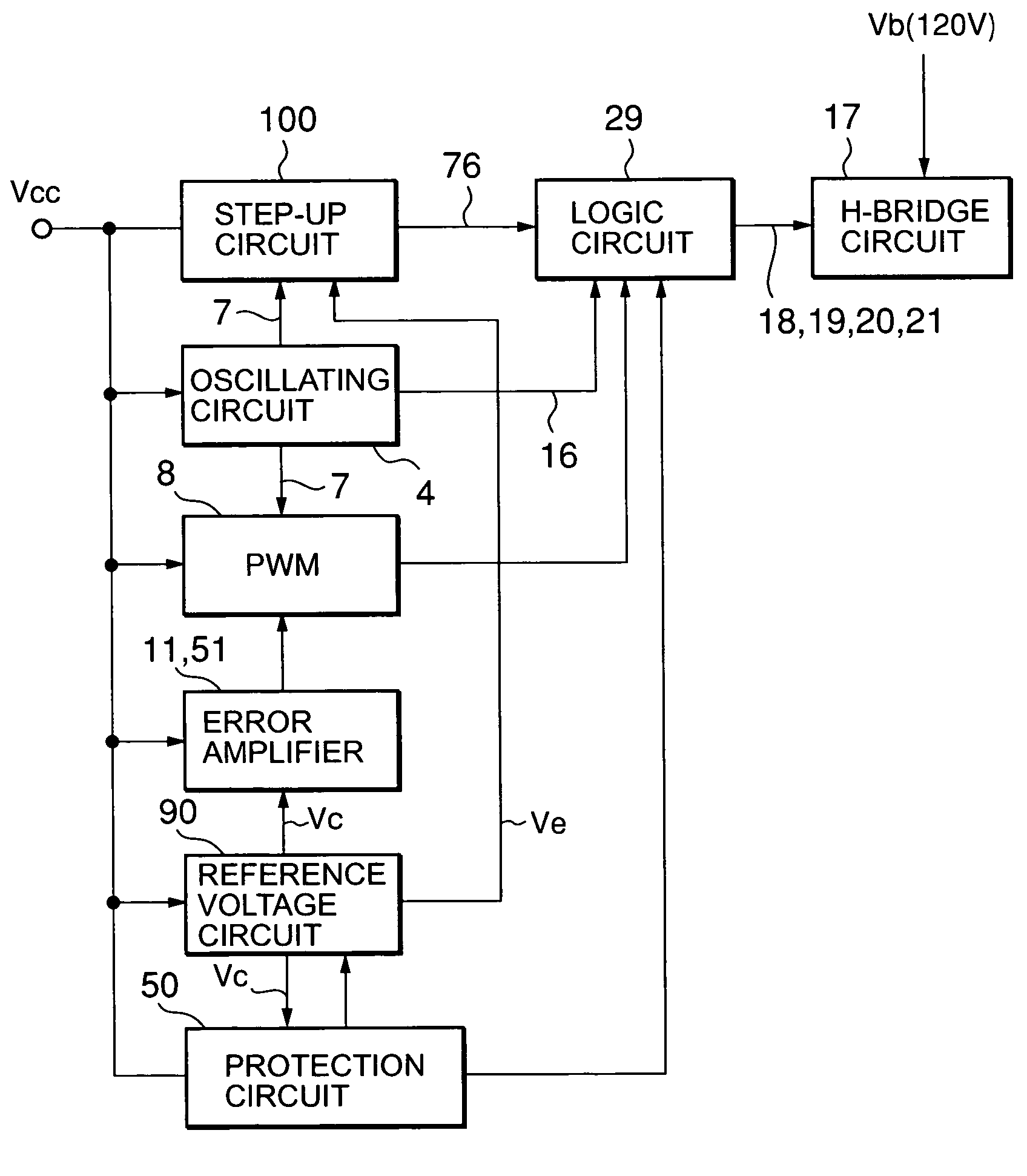
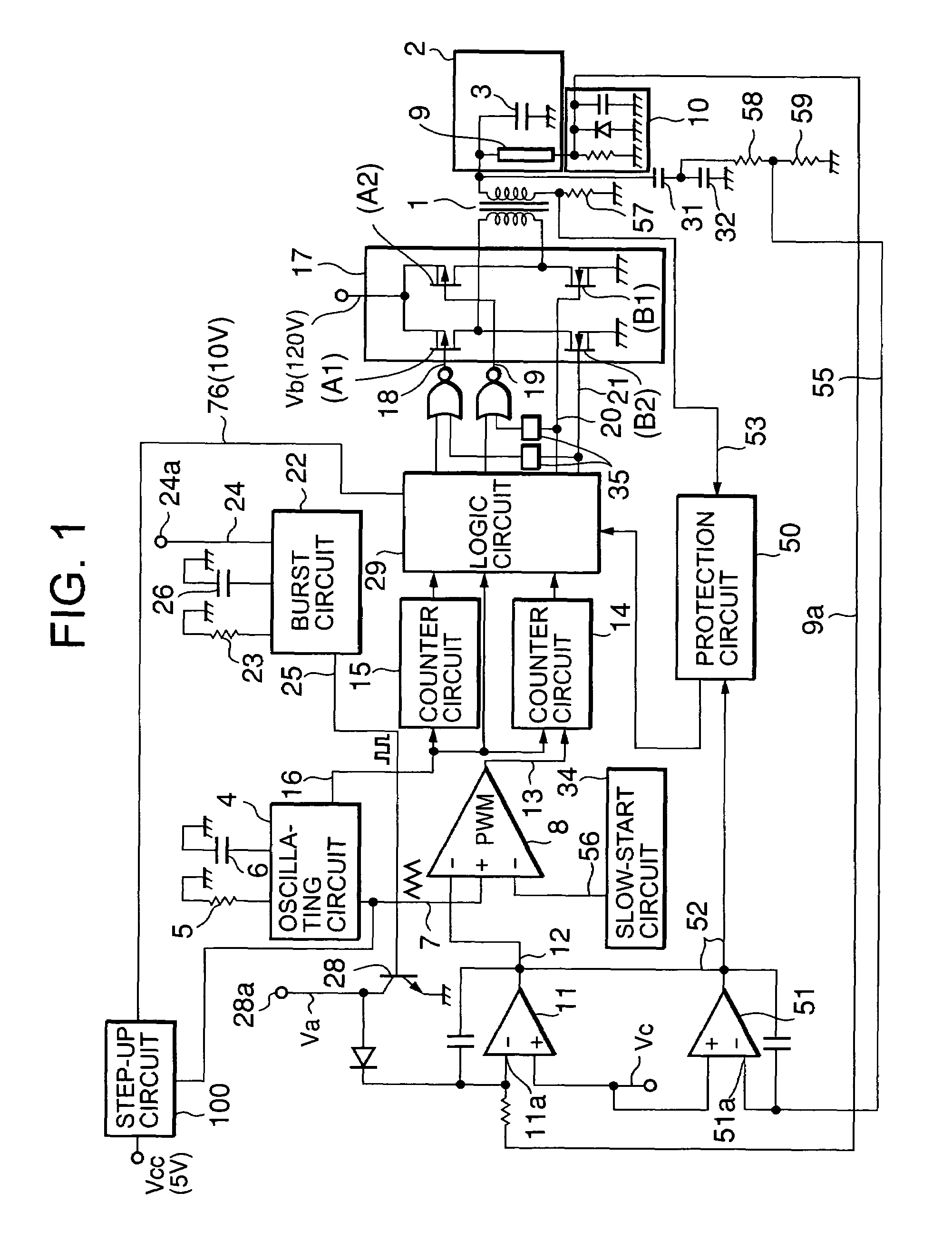
[0026]A block diagram of an inverter circuit for discharge lamps according to an embodiment of the present invention is shown in FIG. 1. For easier understanding, an explanation will be first made on a case where a predetermined voltage Va of a terminal 28a is not applied to an inverting input terminal 11a of an error amplifier 11 thus light modulation does not occur.

[0027]An output of a chopping wave 7 of an oscillating circuit 4 is inputted to a PWM circuit 8. A discharge lamp 9 for backlighting a liquid crystal display (LCD) is disposed in an LCD unit 2 provided at a secondary side of a transformer 1 (in practice, a plurality of discharge lamps and transformers are used, but only one each thereof is illustrated for the purpose of explanation), and its voltage 9a is inputted to the aforementioned inverting input terminal 11a of the error amplifier 11 by m...


PUM


Abstract

An inverter circuit for lighting discharge lamps with reduced power consumption is disclosed. The inverter circuit comprises: a transformer having a resonant circuit formed by a parasitic capacitance of a discharge lamp; an H-bridge circuit to drive a primary side of the transformer at a frequency which is less than a series resonant frequency of the resonant circuit, and at which phase difference in voltage and current at the primary side of the transformer falls within a predetermined range from its minimum; a logic circuit to produce, based on an output signal of an oscillating circuit, gate signals for driving the H-bridge circuit; and a step-up circuit to step up a DC supply voltage (Vcc) based on another output signal of the oscillating circuit, and to supply the logic circuit with the stepped up DC voltage as a supply voltage for producing the gate signals.

Description

This application claims priority from Japan Application No. 2003-199387, filed Jul. 18, 2003 (incorporated by reference herein).BACKGROUND OF THE INVENTION[0001]1. Field of the Invention[0002]The present invention relates to an inverter circuit for lighting discharge lamps for use in a liquid crystal display unit, and the like, and particularly to an inverter circuit with a high power efficiency.[0003]2. Description of the Related Art[0004]In some conventional inverter circuits for lighting discharge lamps, a resonant circuit may be formed by leakage inductance at the secondary side of a transformer and by parasitic capacitance in a discharge lamp connected as load, and the primary side of the transformer may be driven by a resonant frequency of the resonant circuit thus formed. An example of such inverter circuits is disclosed in U.S. Pat. No. 6,114,814. Such a conventional inverter circuit to drive the primary side by the resonant frequency involves phase difference in voltage and...

Claims


Application Information

Patent Timeline
Patent Type & Authority Patents(United States)
IPC IPC(8): H05B37/02H05B41/24H02M1/088H05B41/282H05B41/285H05B41/392
CPCH02M1/088H02M7/53871H05B41/2828H05B41/2855H05B41/3927H02M2001/0006Y02B70/1441H02M2007/4815H02M1/0006H02M7/4815Y02B70/10
Inventor SUZUKI, SHINICHI
Owner MINEBEA CO LTD
Why Eureka
Try Eureka