Composite fuse element and methods of making same

a fuse element and composite technology, applied in the field of fuse elements, can solve the problems of circuit damage, circuit damage, arcing, etc., and achieve the effect of increasing and speeding up the ability of arc quenching

Active Publication Date: 2007-09-11
AEM COMPONENTS (SUZHOU) CO LTD
View PDF28 Cites 12 Cited by
  • Summary
  • Abstract
  • Description
  • Claims
  • Application Information

AI Technical Summary

Benefits of technology

[0007]The invention addresses the above and other needs by providing an improved fuse element made from a composition of conductive material(s) and arc suppressing material(s) such that the contact surface area between the conductive material(s) and arc suppressing material(s) is increased, thereby providing increased and faster arc quenching capability.
[0008]In one embodiment, a fuse element is made from a composition of conductive metals and / or alloys and one or more arc suppressing materials. The mixed materials are bonded together to form an electrically conductive network of conductive particles (e.g., from a powder) with arc suppressing material particles (e.g., from a powder) mixed with and embedded inside the network of conductive particles. Thus, conductive materials and arc suppressing materials are mixed and come in contact with one another at a particle level or a microscopic scale. This inter-connected network of particles provides a larger contact surface area between the conductive materials and the arc suppressing materials. Consequently, when the fuse element melts, vaporizes, and forms the arc, the arc suppressing materials can quench an arc in a very short time because of a shorter diffusion distance between the metal vapors and arc suppressing materials.

Problems solved by technology

Electronic devices, however, often contain circuitry or components that may be sensitive to certain levels of current.
The occurrence of over-current conditions may result in damage to or destruction of the circuitry or components of the electronic device.
Occasionally, however, when the fuse element melts and vaporizes, arcing occurs.
It can allow undesired current levels to reach the circuit to be protected, potentially causing damage to the circuit.
One limitation of such conventional fuse designs, however, is the limited contact surface area between the fuse element and the arc suppressing material(s).
Because of the limited contact surface area between the conductive material(s) and surrounding arc suppressing material(s), the time it takes for the arc suppressing materials to cut off or quench an arc resulting from a high current load on the fuse element may be unduly long, potentially allowing high current levels to reach an electronic circuit or component to be protected.

Method used


Image

  • Composite fuse element and methods of making same
  • Composite fuse element and methods of making same
  • Composite fuse element and methods of making same

Examples


Embodiment Construction

[0014]The invention, in accordance with various preferred embodiments, is described in detail below with reference to the figures, wherein like elements are referenced with like numerals throughout.

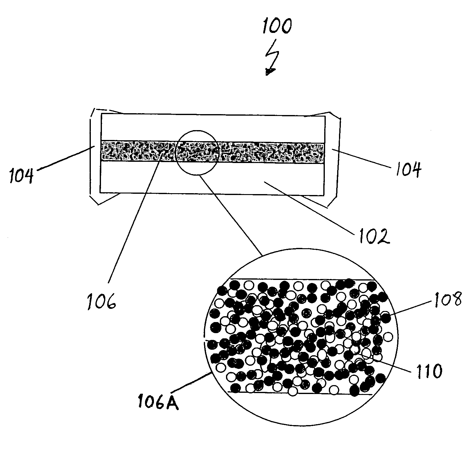
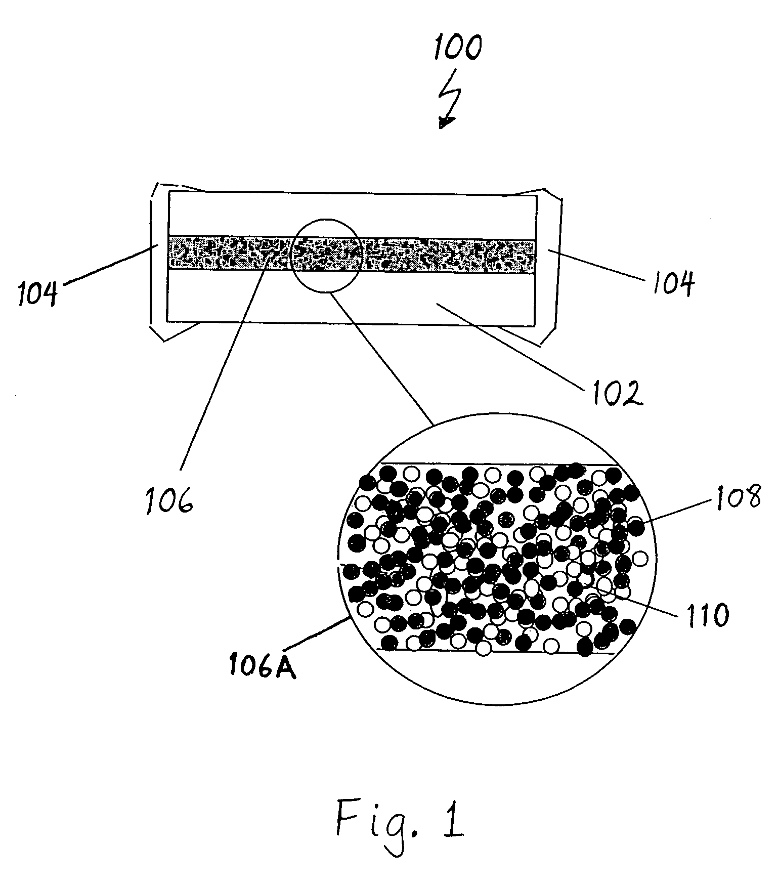
[0015]FIG. 1 illustrates a cross-sectional side view of a fuse 100 in accordance with one embodiment of the invention. The fuse 100 includes a fuse body 102 made from one or more layers of insulating material, such as glass ceramics, glass bond alumina or silicate, glass, ceramic materials, polymer materials with fire retardants, or other known suitable insulating materials. Two electrically conductive contact terminals 104 are positioned at opposite ends of the fuse body 102 to provide electrically conductive contacts to each end of a fuse element 106 disposed within the fuse body 104 and between the two contact terminals 104.

[0016]A cross-sectional portion of the fuse element 106 is magnified and shown within the circular region 106A of FIG. 1. As shown in circular region 106A, the fuse...


PUM

PropertyMeasurementUnit
diameteraaaaaaaaaa
temperatureaaaaaaaaaa
particle sizesaaaaaaaaaa

Abstract

A composite fuse element includes a network or matrix of conductive material that is in contact and interspersed with arc suppressing materials at a particle level. In such a matrix, the conductive (e.g., metal) network and the arc suppressing material particles provides a large contact surface area between these materials. When the conductive network melts or vaporizes, the resulting conductive vapors are adsorbed into the arc suppressing particles in a short time due to the large contact area between conductive and arc suppressing materials and the short diffusion distance that the conductive vapors are required to travel before they are absorbed by the arc suppressing material.

Description

BACKGROUND OF THE INVENTION[0001]1. Field of the Invention[0002]The present invention relates to fuses for protecting electrical circuits from high-current levels and, more particularly, to a fuse element that is made from a composition of conductive and arc suppressing materials.[0003]2. Description of Related Art[0004]Our contemporary society enjoys the convenience and utility offered by the plethora of modern electronic devices available to industry, businesses and consumers. Electronic devices, however, often contain circuitry or components that may be sensitive to certain levels of current. Spikes or otherwise higher-than-nominal current levels are often referred to as over-current conditions. The occurrence of over-current conditions may result in damage to or destruction of the circuitry or components of the electronic device. As a result, designers often utilize fuses to shield the circuitry from such conditions.[0005]Fuses are well known and widely used for over-current pro...

Claims


Application Information

Patent Timeline
Patent Type & Authority Patents(United States)
IPC IPC(8): H01H85/06H01H85/38
CPCH01H85/06H01H85/38H01H2085/388
Inventor LI, XIANG-MINGWANG, LIWUMONTGOMERY, JEFFREY D.CHANG, DANIEL H.
Owner AEM COMPONENTS (SUZHOU) CO LTD
Why Eureka
Try Eureka