
Small rectenna for radio frequency identification transponder

Inactive Publication Date: 2007-09-11
SAMSUNG ELECTRONICS CO LTD
View PDF15 Cites 22 Cited by
  • Summary
  • Abstract
  • Description
  • Claims
  • Application Information

AI Technical Summary

Benefits of technology

[0017]The present invention provides a rectenna with an electrically small conjugate matched antenna having an enhanced gain for a overall increased bandwidth without strongly affecting polarization and RCS characteristics.

Problems solved by technology

The reason being is that, currently, an antenna size of even a quarter of a wavelength is precluded from many applications.
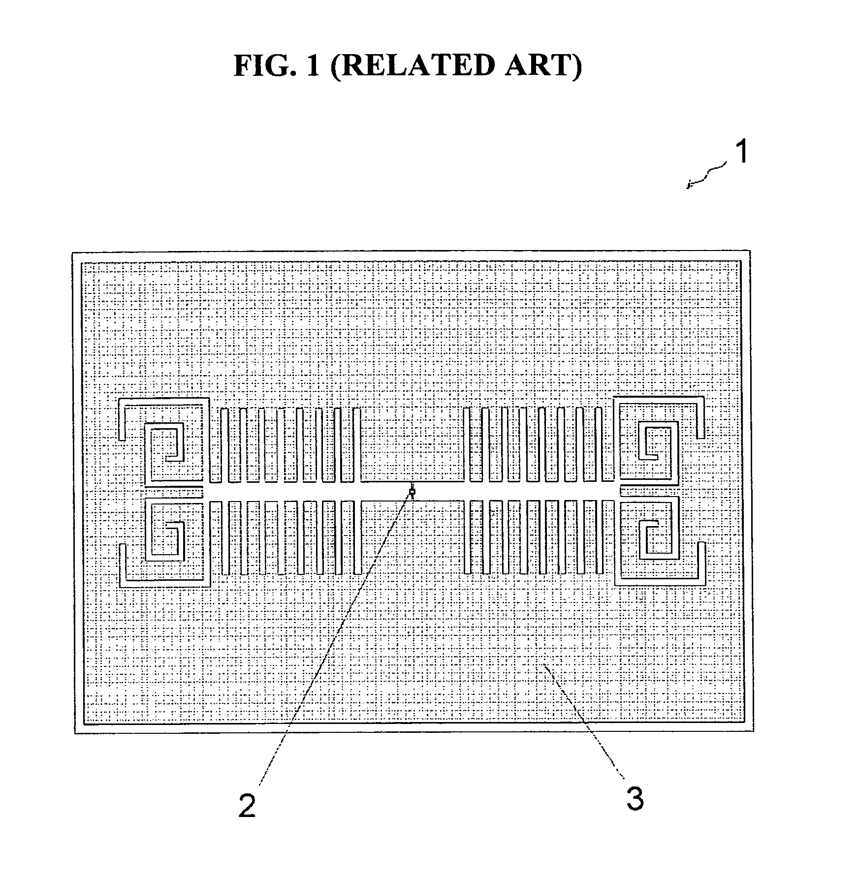
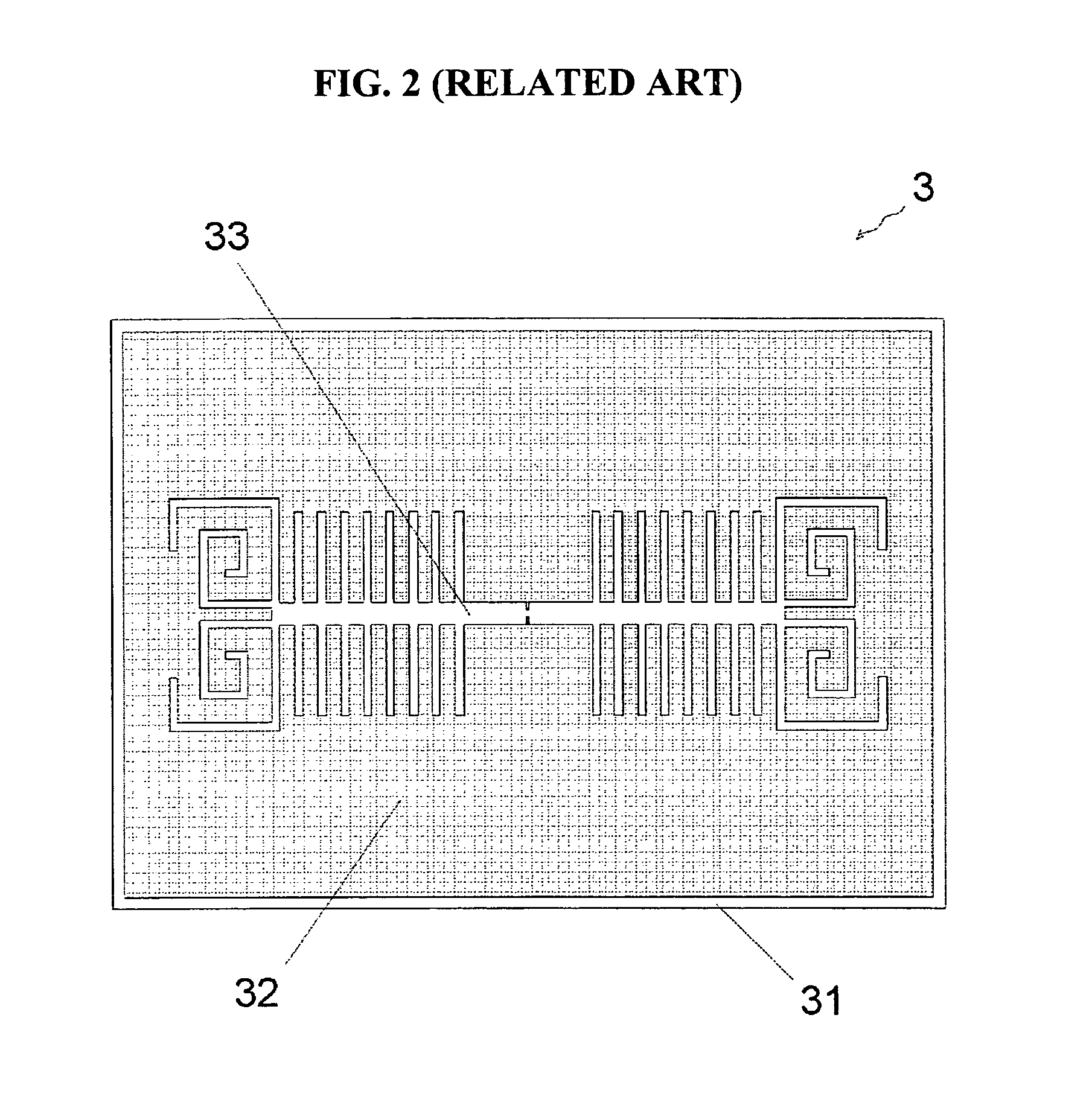
The direct implementation of the antenna described in Korea Patent Application No. 10-2005-0026496 for an RFID transponder design faces important challenges.
Specifically, the mismatch very strongly affects a read range, i.e., a maximum operating distance between a reader and a transponder since the power radiated by the reader is rather limited due to certain safety regulations and other legislation.
A rectifying circuit is within an ASIC and includes diodes, such as Schottky diodes, and capacitors, resulting in a complex input impedance with substantial capacitive reactance.

Method used


Image

  • Small rectenna for radio frequency identification transponder
  • Small rectenna for radio frequency identification transponder
  • Small rectenna for radio frequency identification transponder

Examples


Embodiment Construction

[0037]Reference will now be made in detail to exemplary embodiments of the present invention, examples of which are illustrated in the accompanying drawings, wherein like reference numerals refer to the like elements throughout. The exemplary embodiments are described below in order to explain the present invention by referring to the figures.

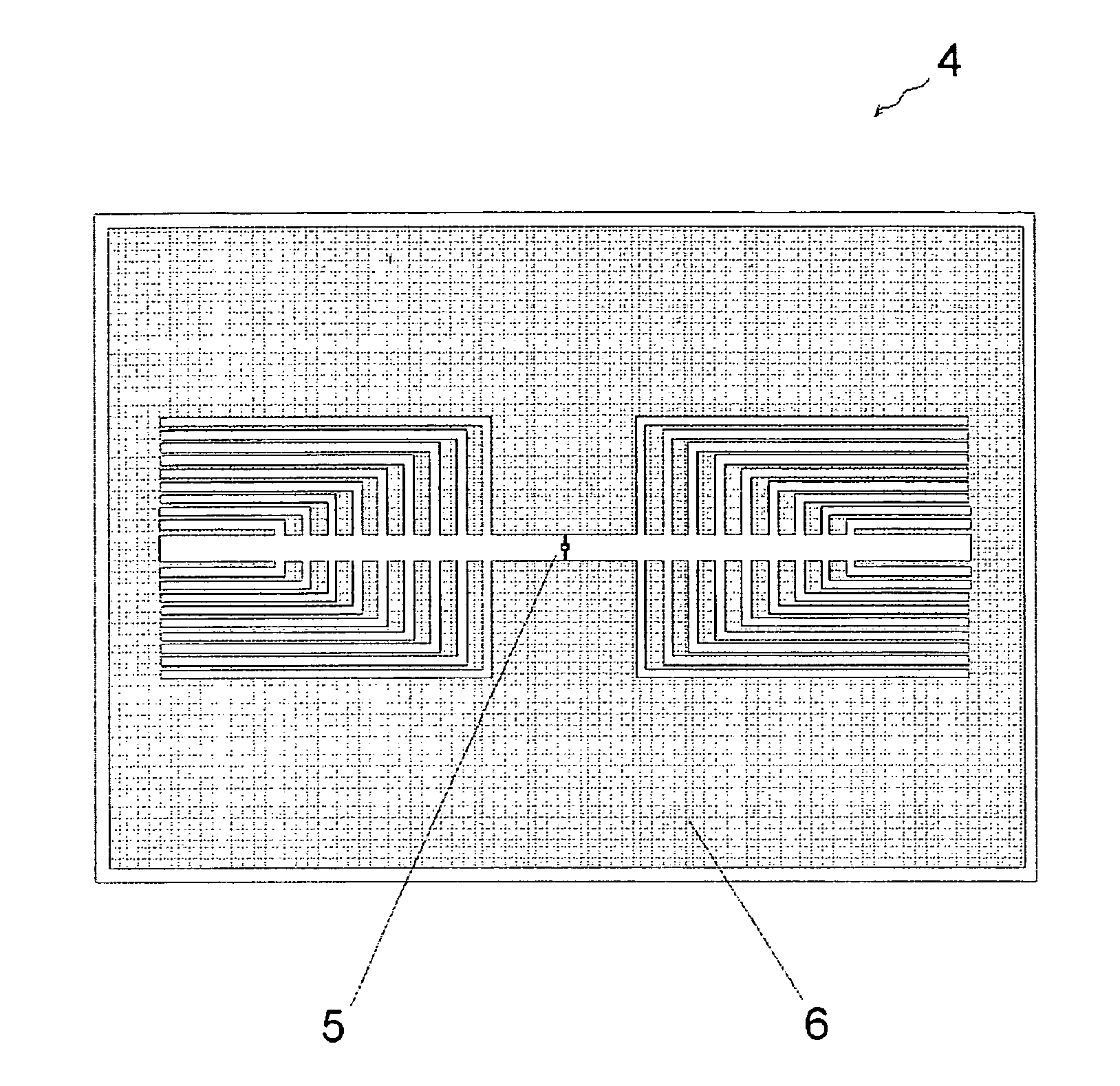
[0038]FIG. 4 is a diagram illustrating a small rectenna 4 according to an exemplary embodiment of the present invention. The rectenna 4 includes a rectifying circuit embedded into an ASIC 5 of the transponder and a connected antenna 6.

[0039]FIG. 5 is a diagram illustrating the antenna 6 of the small rectenna 4 of FIG. 4 according to an exemplary embodiment of the present invention. The electrically small antenna 6 has a dielectric substrate 61; a thin conductive layer 62 formed on a top surface of the substrate 61; and a slot pattern 63 within the conductive layer 62. The conductive layer 62 with the slot pattern 63 constitutes a radiating part...


PUM


Abstract

A small rectenna including a thin conductive layer formed on a surface of a dielectric substrate and a slot pattern arranged within the thin conductive layer. The small rectenna for an RFID transponder includes: a dielectric substrate; a thin conductive layer formed on a surface of the dielectric substrate; a slot pattern configured within the thin conductive layer so that the rectenna has an enhanced gain and a greater operating bandwidth; and an inlet of an electronic chip including an ASIC in the slot pattern.

Description

CROSS-REFERENCE TO RELATED APPLICATION[0001]This application claims priority from Korean Patent Application No. 10-2006-0047549, filed on May 26, 2006, in the Korean Intellectual Property Office, the disclosure of which is incorporated herein by reference.BACKGROUND OF THE INVENTION[0002]1. Field of the Invention[0003]Apparatuses consistent with the present invention relate to a radio frequency and a microwave rectenna, and more particularly to an electrically small antenna in combination with an electronic chip of a radio frequency identification (RFID) transponder.[0004]2. Description of Related Art[0005]An RFID transponder is a tag device that can respond to being read by sending a content of its embedded memory by backscatter communication to an interrogator, i.e. a reader. A passive RFID transponder has no battery; instead, it gets all the needed energy to send a signal to the reader, from a carrier signal of the reader.[0006]Generally, the RFID transponder includes an applicat...

Claims


Application Information

Patent Timeline
IPC IPC(8): H01Q1/38
CPCH01Q1/2208H01Q1/38H01Q1/248H04B5/77
Inventor TIKHOV, YURIMIN, YOUNG-HOONKIM, YOUNG-EIL
Owner SAMSUNG ELECTRONICS CO LTD
Learn More