
Sharpening a digital image in accordance with magnification values

a digital image and magnification value technology, applied in image enhancement, instruments, computing, etc., can solve the problems of sharpening, affecting the spatial frequency of the print, and pixel sharpening, so as to improve the quality of the output print, reduce computational complexity, and improve the effect of output quality

Inactive Publication Date: 2007-09-11
MONUMENT PEAK VENTURES LLC
View PDF16 Cites 18 Cited by
  • Summary
  • Abstract
  • Description
  • Claims
  • Application Information

AI Technical Summary

Benefits of technology

This approach ensures high-quality prints by adjusting sharpness based on actual print magnification, reducing computational complexity and minimizing noise amplification, while maintaining consistent spatial frequency response across different print sizes.

Problems solved by technology

If a digital sharpening process is applied without knowing the magnification required to generate a print, there is no way of knowing which spatial frequencies of the print will be affected.
This in turn requires that more pixels be sharpened, which is inefficient.
Another problem associated with sharpening digital images is that sharpening amplifies noise and other artifacts—e.g. the artifacts associated with JPEG compression, which is commonly used to reduce the file size of an image.
In addition, Gouch's sharpening method is not designed to minimize the amplification of compression artifacts.
While these methods do indeed sharpen the image while attempting to minimize noise amplification, they are computationally complex.
In addition, Shimazaki's sharpening method is not designed to minimize the amplification of compression artifacts.
In addition, Gallagher's sharpening method is not designed to minimize the amplification of compression artifacts.
However, the Keyes method only varies the gain of a fixed filter.
Unfortunately, this method produces sub-optimal effects for different spatial frequencies because the frequency response of the lowpass filter is constant.
In addition, the Keyes sharpening method is not designed to minimize the amplification of compression artifacts.
However, the authors do not describe an efficient method for generating the filter for images having various numbers of rows and column of pixels.
In addition, the method is not designed to minimize the amplification of compression artifacts.
The method does not ensure that the image sharpening properly enhances the desired spatial frequencies of an output print.
In addition, the method does not prevent the amplification of compression artifacts.

Method used


Image

  • Sharpening a digital image in accordance with magnification values
  • Sharpening a digital image in accordance with magnification values
  • Sharpening a digital image in accordance with magnification values

Examples


Embodiment Construction

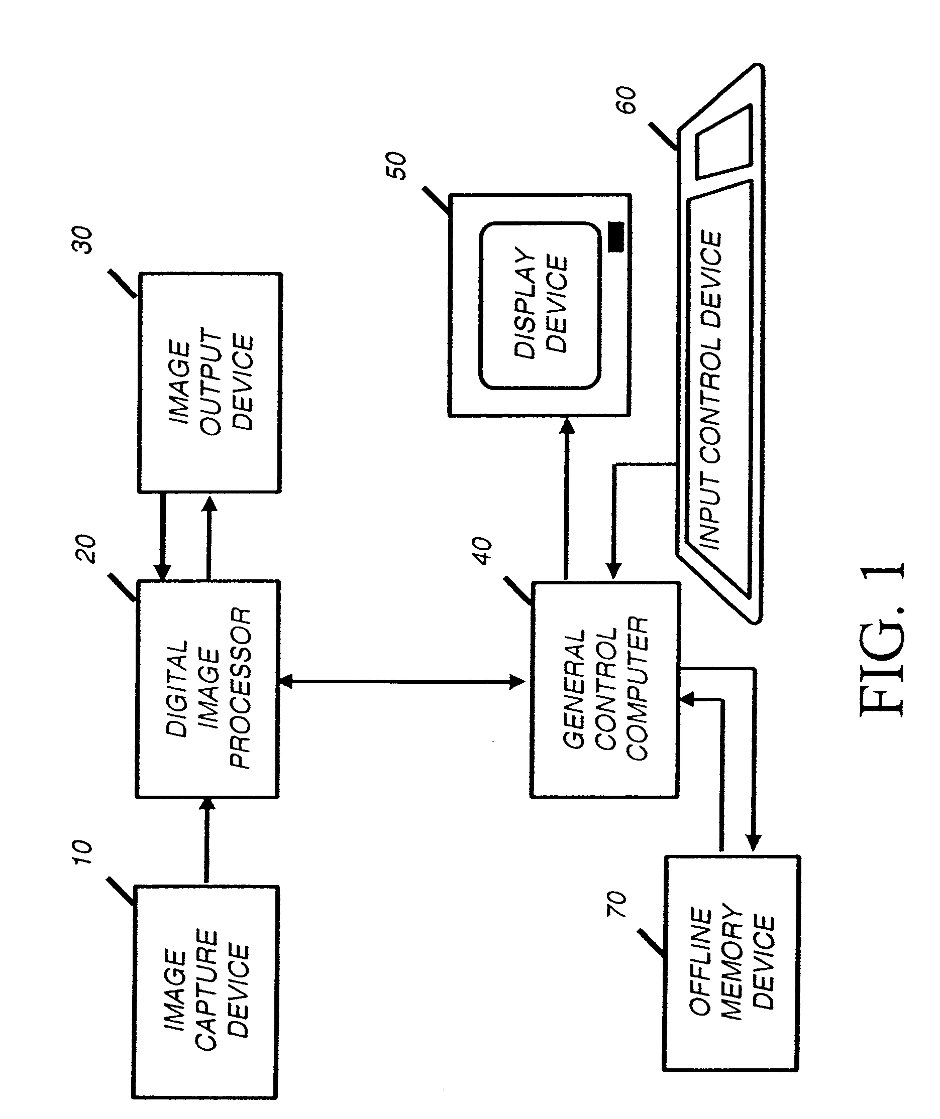
[0036]In the following description, a preferred embodiment of the present invention will be described as a software program. Those skilled in the art will readily recognize that the equivalent of such software may also be constructed in hardware. Because image manipulation algorithms and systems are well known, the present description will be directed in particular to algorithms and systems forming part of, or cooperating more directly with, the method in accordance with the present invention. Other aspects of such algorithms and systems, and hardware and / or software for producing and otherwise processing the image signals involved therewith, not specifically shown or described herein may be selected from such systems, algorithms, components, and elements known in the art. Given the description as set forth in the following specification, all software implementation thereof is conventional and within the ordinary skill in such arts.

[0037]The present invention may be implemented in c...


PUM


Abstract

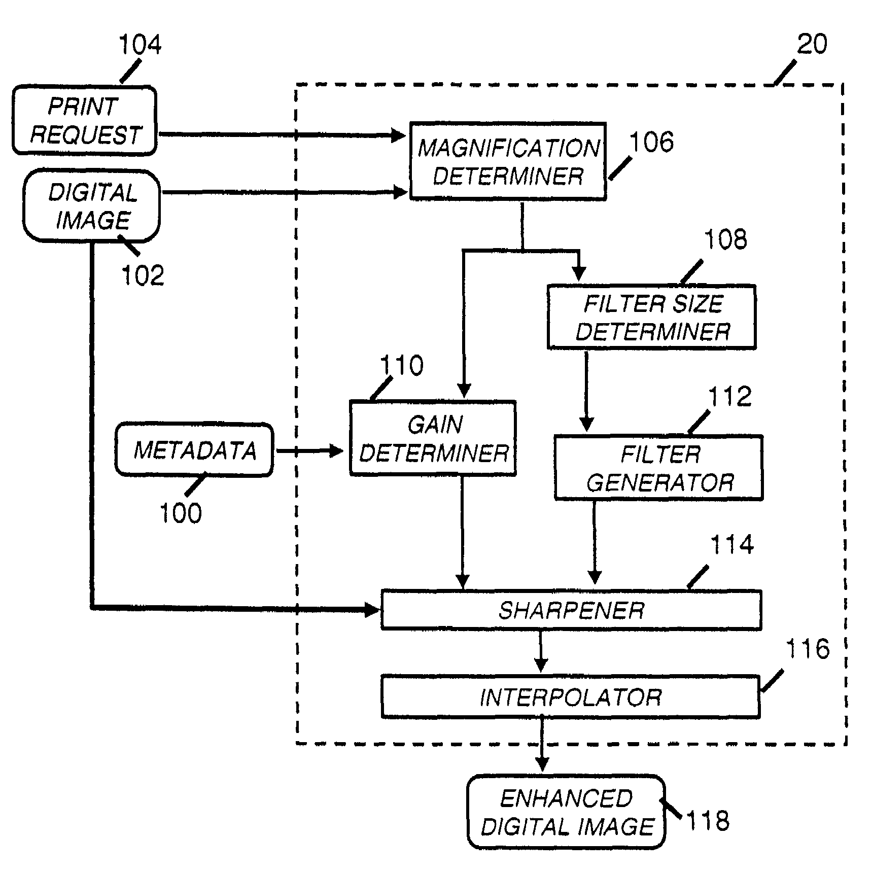
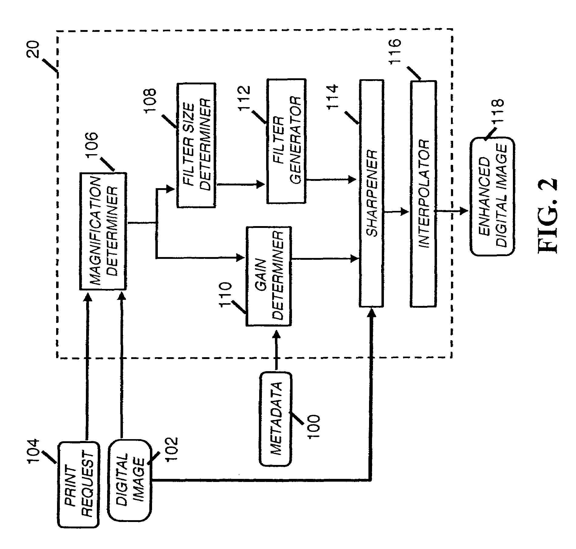
A method of processing a digital image having pixels to improve the sharpness of a print generated from the digital image including determining a magnification value representing the magnification of a pixel of the digital image on the print based on the number of input digital image pixels and the output number of digital image pixels; producing a filter in response to the magnification value; using the filter to operate on the digital image to adjust the sharpness of the digital image to produce a sharpened digital image; resizing according to the magnification value the sharpened digital image to produce a resized sharpened digital image which includes the output number of digital image pixels; and producing the print based on the resized sharpened digital image.

Description

FIELD OF INVENTION[0001]The present invention relates to an improved method of sharpening a digital image for printing.BACKGROUND OF THE INVENTION[0002]In processing a digital image, it is common to sharpen the image to enhance fine detail with sharpening algorithms. Typically, sharpening is performed by a convolution process (for example, see A. K. Jain, Fundamentals of Digital Image Processing, Prentice-Hall: 1989, pp. 249-251). The process of unsharp masking is an example of a convolution-based sharpening process. For example, sharpening an image with unsharp masking can be described by the equation:s(x,y)=i(x,y)**b(x,y)+βf(i(x,y)−i(x,y)**b(x,y))   (0)where:[0003]s(x,y)=output image with enhanced sharpness[0004]i(x,y)=original input image[0005]b(x,y)=lowpass filter[0006]β=unsharp mask gain factor[0007]f( )=fringe function[0008]** denotes two dimensional convolution[0009](x,y) denotes the xth row and the yth column of an image[0010]Typically, an unsharp image is generated by convo...

Claims


Application Information

Patent Timeline
Patent Type & Authority Patents(United States)
IPC IPC(8): G06K9/32G06T5/00G06T5/50G06V10/30H04N1/393H04N1/58
CPCG06K9/40G06T5/004H04N1/393H04N1/58G06V10/30G06T5/75
Inventor BRAUN, GUSTAV J.GALLAGHER, ANDREW C.PTUCHA, RAYMOND W.
Owner MONUMENT PEAK VENTURES LLC
Learn More