Scalable thermal control system for spacecraft mounted instrumentation

a technology for spacecraft and instrumentation, applied in the direction of cosmonautic thermal protection, cosmonautic vehicles, transportation and packaging, etc., can solve the problem of increasing the launch cost and reducing the number of spacecraft, and increasing the cost of launch, etc. problem, to achieve the effect of reducing the impact of cooler-induced mechanical vibration

Inactive Publication Date: 2007-09-18
LOCKHEED MARTIN CORP
View PDF11 Cites 25 Cited by
  • Summary
  • Abstract
  • Description
  • Claims
  • Application Information

AI Technical Summary

Benefits of technology

[0011]The disclosure solves the above-stated problems of prior-art GEO remote sensing spacecraft by providing a scaleable instrument thermal control arrangement incorporated into the spacecraft design. An exemplary spacecraft in which the thermal control arrangement may be implemented is characterized in part by a spacecraft bus supporting an instrument accommodation platform on which is mounted at least one instrument tending to generate heat, and spacecraft thermal radiator panels spatially separated from at least one instrument. The arrangement comprises at least one active cooler, such as a cryocooler, mounted to the spacecraft at a location spatially separated from the instrument and platform, in which the active cooler is thermally linked to one of the spacecraft thermal radiator panels for removal of active cooler waste heat: This physical separation of the coolers from the instruments reduces the impact of cooler-induced mechanical vibrations.

Problems solved by technology

A drawback of multi-sat architecture is that it requires at least twice as many spacecraft to implement, compared to current “large-sat” architecture.
If the spacecraft are so heavy that they require dedicated launches, then the increased launch cost might render the multi-sat architecture too expensive to implement.
This “balanced” configuration tends to result in small solar pressure disturbance torque and minimal propellant and operational down time needed for momentum control thruster maneuvers.
A disadvantage, however, is that one of the solar arrays will impede the field of-view (FOV) of the instrument passive cryogenic radiators, which prevents achieving the required temperature control of critical focal plane sensor elements.
If instrument focal plane temperatures cannot be maintained, then mission performance will be impacted.
The single wing configuration tends to lead to a large solar pressure torque, large momentum-adjust propellant requirements, frequent (e.g., daily) momentum adjust maneuvers that disrupt instrument operations, and higher RWA speeds that produce larger disturbances and jitter.
And the single wing design considerably limits dual launch payload mass capability because of the need to carry a large amount of momentum adjust propellant.
Another disadvantage of current GOES architecture is that each instrument must include its own thermal radiators and active coolers as necessary to maintain the proper focal plane temperatures.
Also, a GEO spacecraft design includes its own radiators (e.g. the north and south-facing panels), and these radiators are generally underutilized for a GEO remote sensing mission due to overall low thermal dissipation requirements.
The fact that the instruments do not have access to these radiators, and hence must supply their own duplicate radiators, is highly mass inefficient.
Additionally, the present approach to instrument thermal control lacks scalability.
Such temperature variations may possibly degrade measurement accuracy.
Active coolers incorporated in the instruments may produce mechanical vibrations that can impact the measurement accuracy.
Mitigation of these vibration effects may complicate instrument designs and increase cost.

Method used


Image

  • Scalable thermal control system for spacecraft mounted instrumentation
  • Scalable thermal control system for spacecraft mounted instrumentation
  • Scalable thermal control system for spacecraft mounted instrumentation

Examples


Embodiment Construction

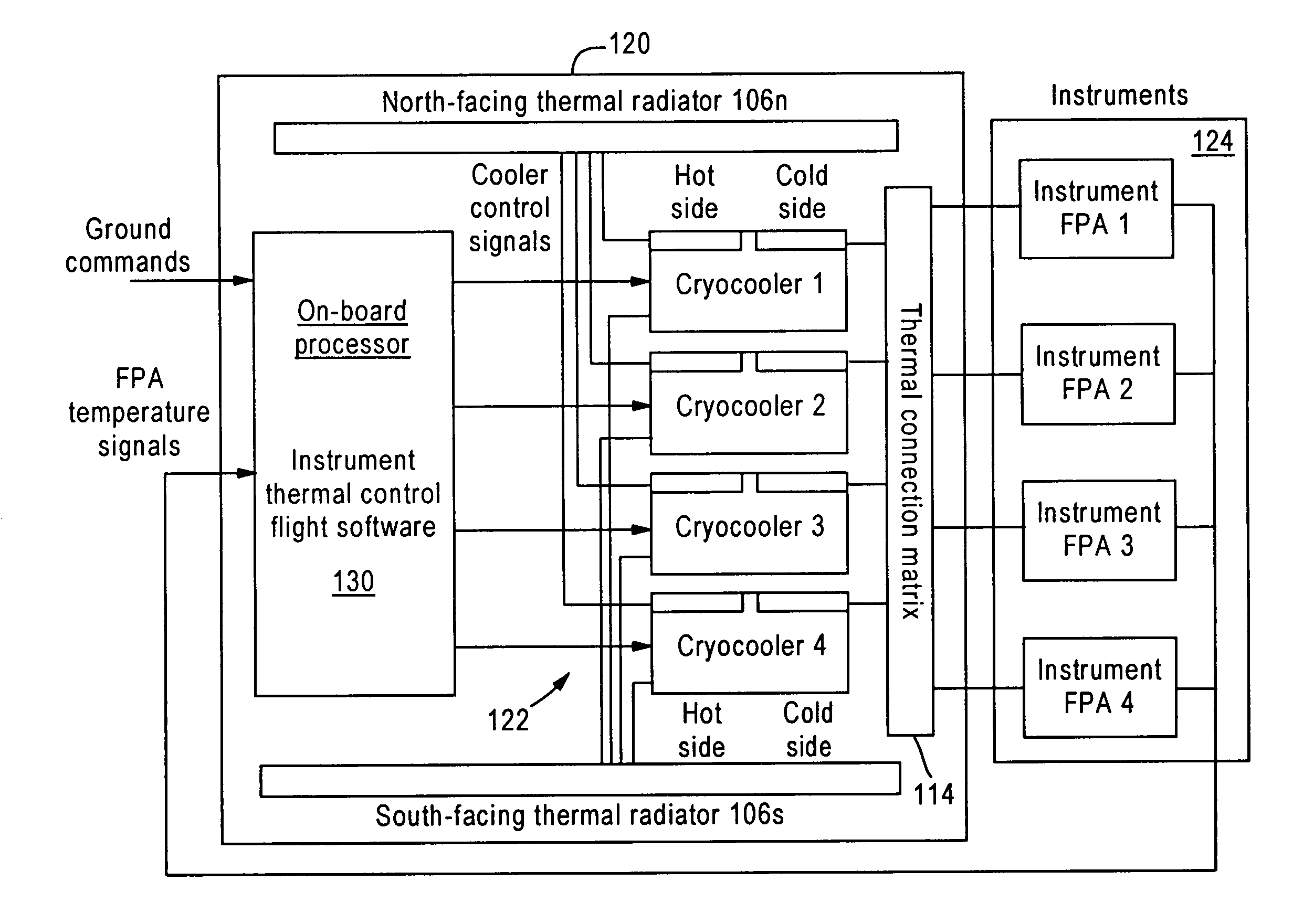
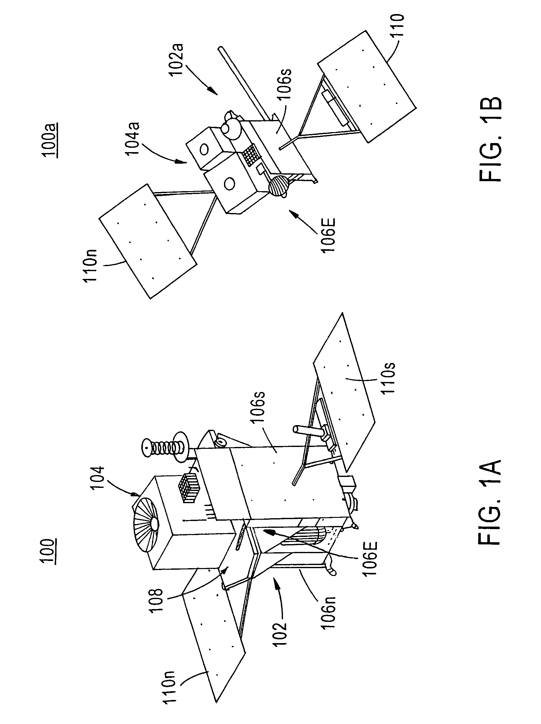
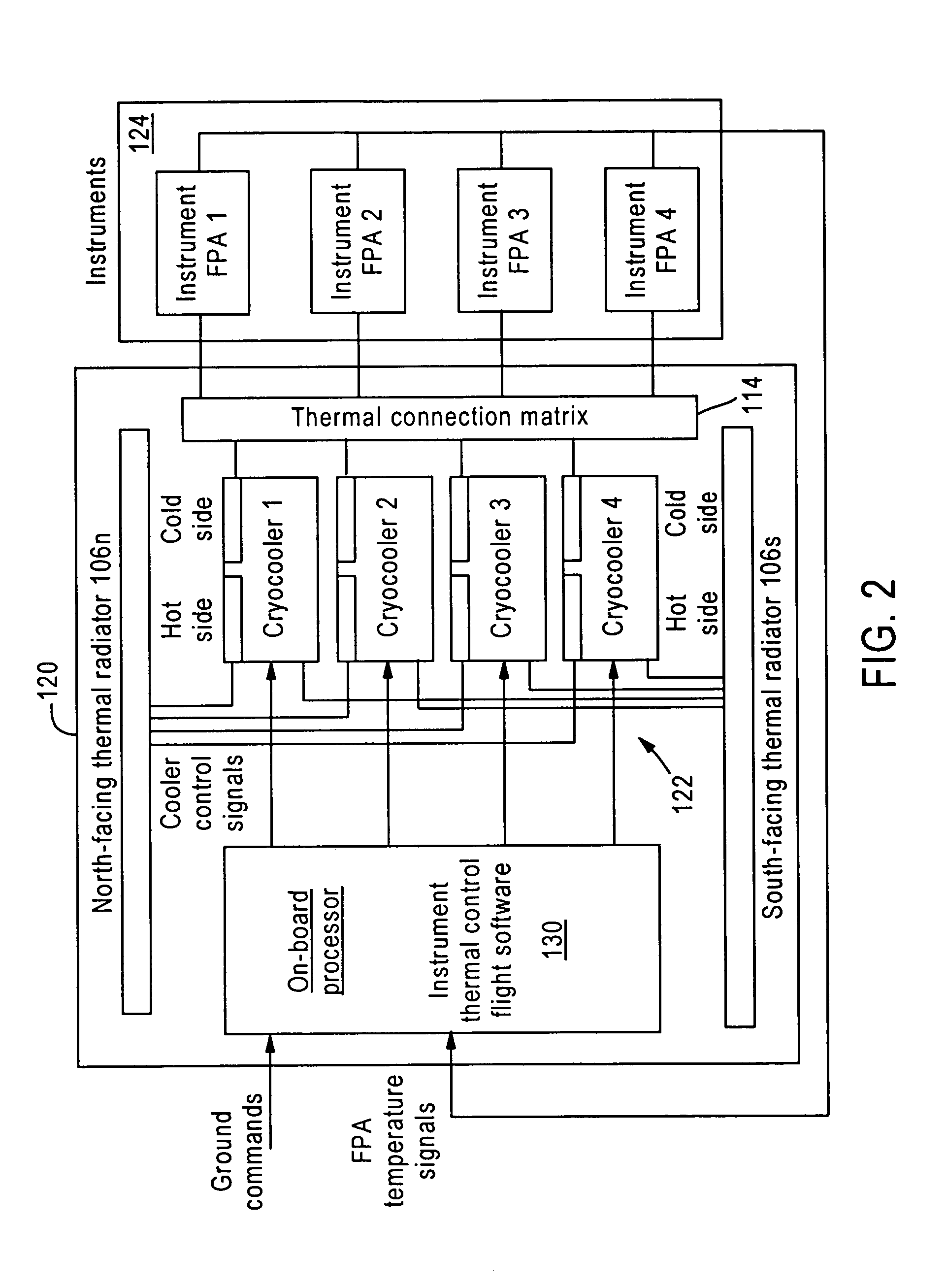
[0021]The instrument thermal control system and methodology described herein is applicable generally to any spacecraft, but has particular applicability to geosynchronous remote sensing satellites, such as NASA's GOES-R spacecraft, two examples of which are shown respectively in FIGS. 1(a) and (b). These spacecraft are similar in that they share a common bus 102, 102a, and carry at least one primary instrument, such as an imager or sounder, but support different instrument combinations. For example, spacecraft 100, shown in FIG. 1(a), may include an advanced baseline imager (ABI) 104, and spacecraft 100a may include instruments from an hyperspectral environment suite (HES) 104a.

[0022]The instruments include focal planes that must be maintained at cryogenic temperatures during operations. For example, an ABI focal plane may be required to operate at 70 deg. K, and an HES focal plane at 55 deg. K. The bus 102, 102a of each spacecraft supports a number of panels, such as thermal radia...


PUM


Abstract

A spacecraft instrument thermal control method and system providing scalable thermal control of on-board instrument temperature. Adapted for a spacecraft with bus supporting instrumentation and thermal radiator panels, cooling is carried out by one or more active coolers, such as cryocoolers, each mounted to the spacecraft at a radiator spatially separated from the instrument, with cold side of the cooler being thermally coupled to an instrument focal plane or other instrument location requiring cryogenic cooling and the warm side coupled to the radiator. A closed loop temperature control system measures the temperature of the controlled portion of the instrument, and adjusts active cooler drive signals to maintain a specified set point temperature.

Description

CROSS-REFERENCES TO RELATED APPLICATIONS[0001]This application claims priority from U.S. Provisional Application No. 60 / 465,012, filed on Apr. 22, 2003, the entire contents of which are incorporated herein by reference.TECHNICAL FIELD[0002]This invention relates generally to spacecraft instrumentation cooling, and more particularly to a novel method and system of doing so implementing active cooling elements.BACKGROUND OF THE INVENTION[0003]Historically, satellite architecture has featured a small number of relatively large spacecraft carrying all instrumentation required to carry out prescribed missions. There is a current trend in some applications, however, toward deployment of a multiple satellite, or “multi-sat” approach, such as envisioned in NASA's GOES-R system architecture featuring smaller spacecraft each incorporating different subsets of instrumentation. The “multi-sat” architecture is advantageous because of its increased implementation and operational flexibility since...

Claims


Application Information

Patent Timeline
Patent Type & Authority Patents(United States)
IPC IPC(8): B64G1/58
CPCB64G1/50B64G1/503
Inventor WONG, HAMILTONGOODZEIT, NEIL
Owner LOCKHEED MARTIN CORP
Why Eureka
Try Eureka