Extruder

a technology of extruder and rotary stirring, which is applied in the direction of mixing/kneading with horizontally mounted tools, clay mixing apparatus, rotary stirring mixer, etc. it can solve the problems of local over-average wear, and achieve the effect of reducing pressur

Active Publication Date: 2007-09-18
BLACH VERWALTUNGS GMBH
View PDF28 Cites 19 Cited by
  • Summary
  • Abstract
  • Description
  • Claims
  • Application Information

AI Technical Summary

Benefits of technology

[0007]The screw portions of the screw element between the ring portions first cause a pressure buildup which then urges the substance through the annular gap between extruder housing and the ring portions with shearing action and elongation, and the pressure is reduced again. The recurring sequence of shear gap passage, pressure buildup, shear gap passage, etc., on the screw elements causes a defined stress on the substance and thus a uniform stress, without unduly stressing the substance or the screw.
[0008]The annular and/or shear gap between

Problems solved by technology

The substance is pressed through a narrow tapered gap between the disk cams and the extruder housing, which can result in

Method used


Image

  • Extruder
  • Extruder
  • Extruder

Examples


Embodiment Construction

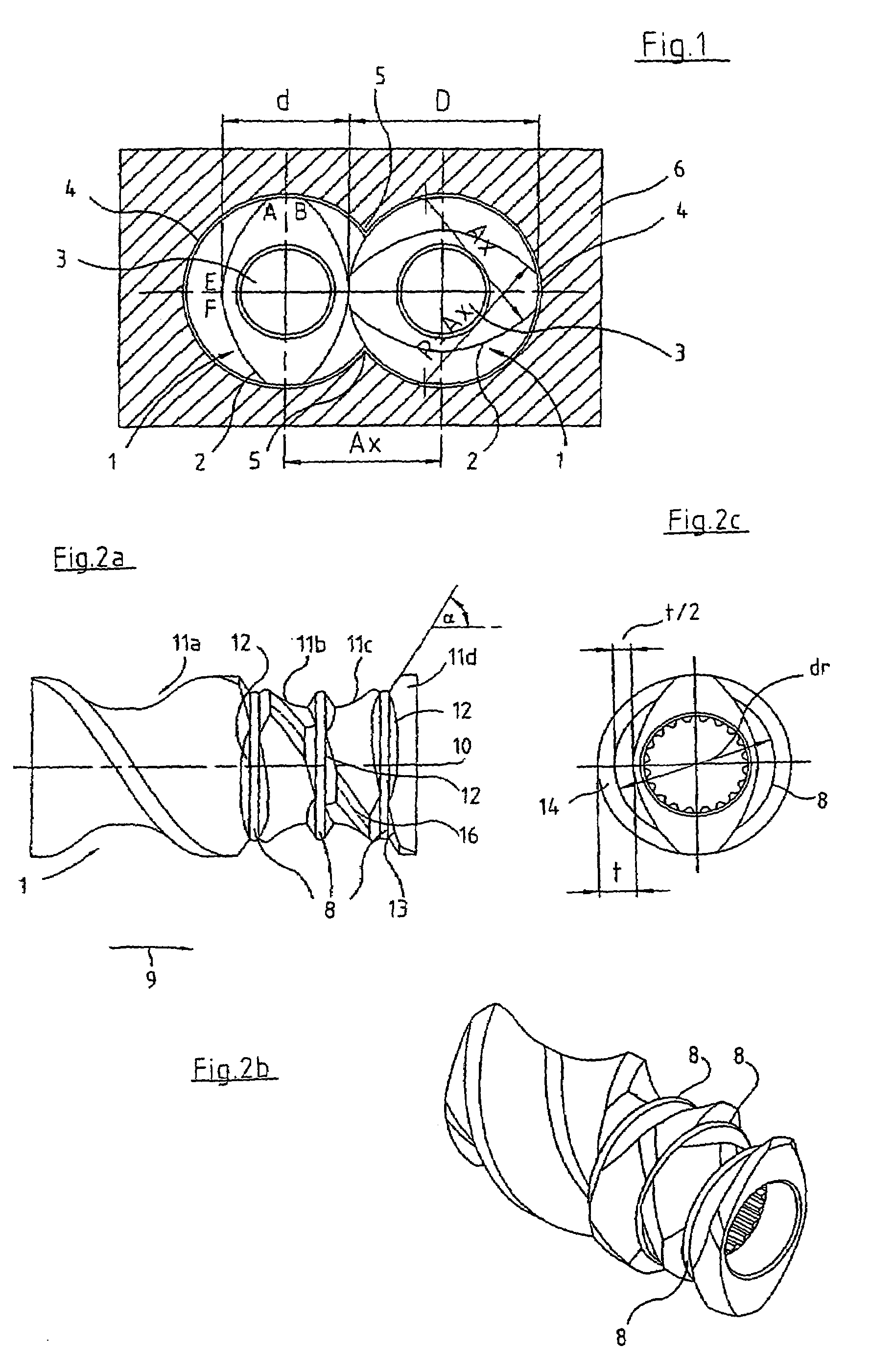
[0021]According to FIG. 1, screw elements 1 have transverse profile 2 composed of three circular arcs A-B, E-F and A-E. Circular arc A-B has a diameter corresponding to outside screw diameter D, circular arc E-F has a diameter corresponding to screw core diameter d, and circular arc A-E has a diameter whose radius corresponds to center distance Ax of the two screw elements 1 (cf. EP-B-0002131).

[0022]Intermeshing screw elements 1 of the twin-shaft extruder are fitted so as to rotate in unison on two parallel, corotating shafts 3 guided on circular segments 4 of extruder housing 6 that are parallel to screw shafts 3, so that two wedges 5 are formed.

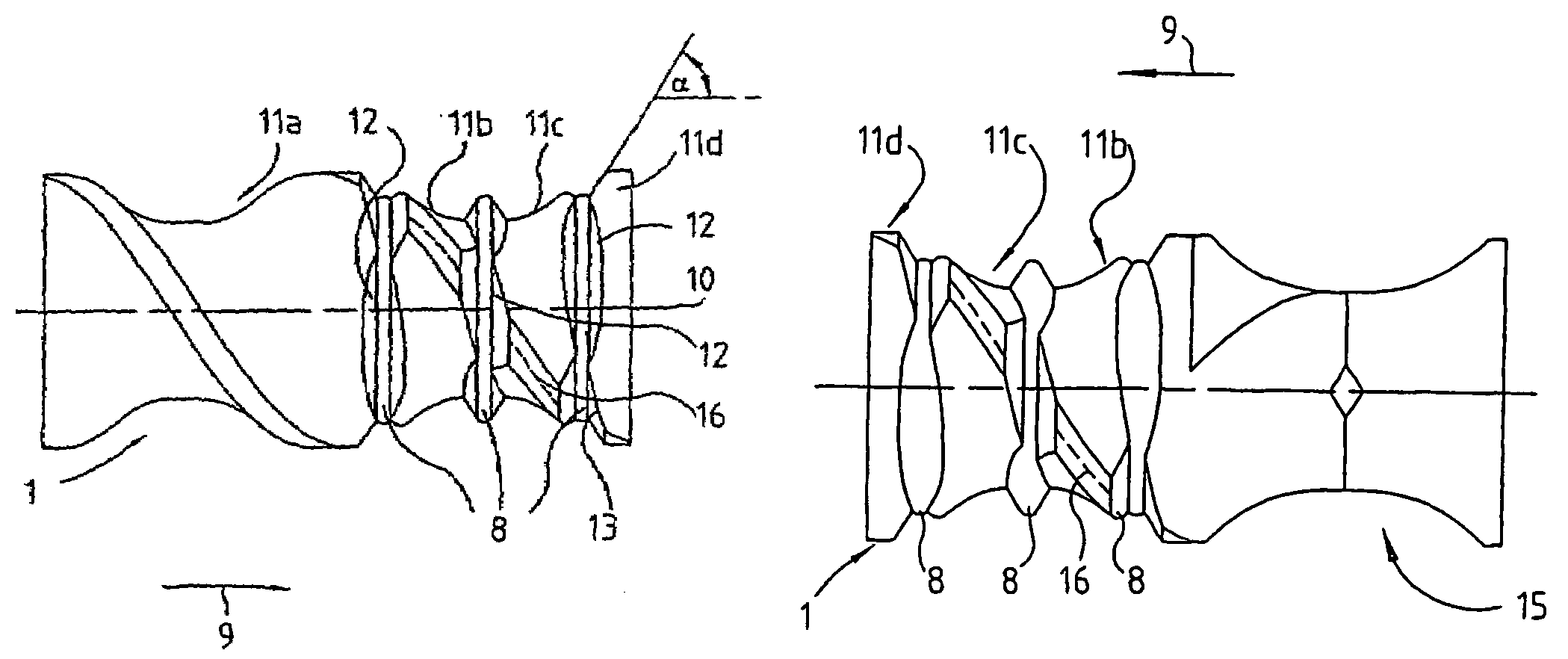
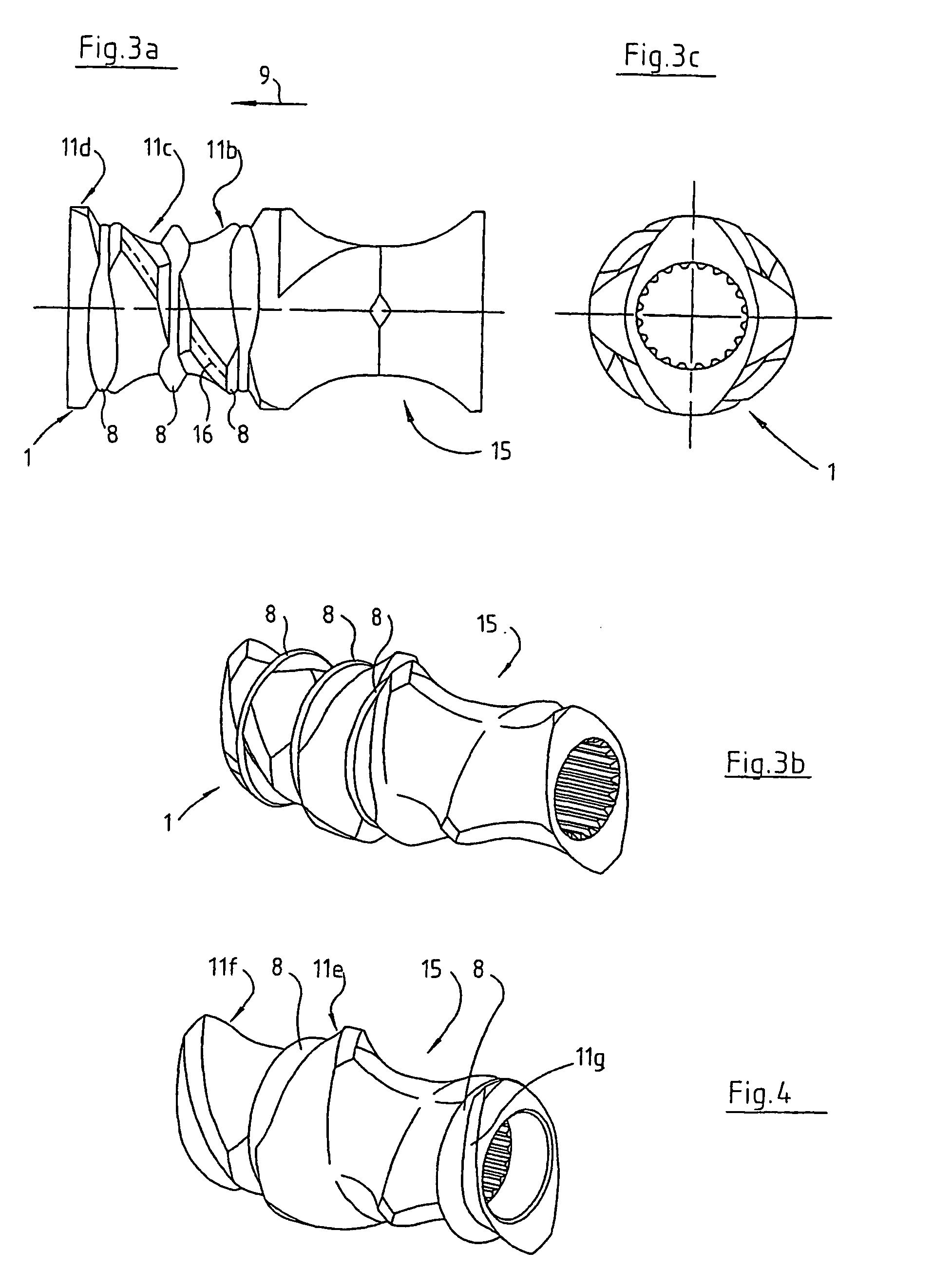
[0023]According to FIGS. 2a to 2c, double-flighted screw element 1 has three ring portions 8 concentric with shaft axis 7 and disposed a distance apart.

[0024]Ring portions 8 are provided on the side of screw element 1 facing the outlet of the extruder here, with respect to the conveying direction shown by arrow 9, i.e. in conveying directio...


PUM

PropertyMeasurementUnit
Fractionaaaaaaaaaa
Fractionaaaaaaaaaa
Massaaaaaaaaaa

Abstract

In an extruder for continuous working and/or processing of flowable substances having at least two parallel, corotating shafts equipped with intermeshing screw elements whose face is limited by circular arcs corresponding to the outside screw diameter, the screw core diameter and at most the center distance of the screw elements, and guided on circular segments of the extruder housing that are parallel to the shafts, at least one screw element (1) has a plurality of concentric ring portions (8) spaced a distance apart and formed by grooves (12) turned into the screw element (1).

Description

FIELD OF THE INVENTION[0001]This invention relates to an extruder for continuous working and / or processing of flowable substances having at least two parallel, co-rotating shafts with intermeshing screw elements.BACKGROUND OF THE INVENTION[0002]For continuous working, i.e. in particular mixing and kneading, of flowable, i.e. liquid, viscous, plastic or particulate, substances, so-called kneading blocks consisting of disk cams disposed offset in the manner of a spiral staircase are used in twin-shaft extruders (cf. DE-C-813154). The substance is pressed through a narrow tapered gap between the disk cams and the extruder housing, which can result in different heating and partial overstressing by shearing of the substance, and further causes locally above-average wear.[0003]DE-A-2 003 593 already discloses a twin-shaft extruder wherein the screw flight of one screw is sealed by a sealing bar while the other screw has a recess at the place in the screw crest that moves past said sealing...

Claims


Application Information

Patent Timeline
IPC IPC(8): B29B7/48B29C47/40A21C1/02A21C1/06B01F7/08B29C48/40B29C48/405B29C48/57B29C48/575B29C48/67
CPCB29B7/481B29C47/0825B29C47/6056B29C47/38B29C47/402B29C47/60B29C47/0861B29C47/0009B29C48/2564B29C48/2517B29C48/402B29C48/57B29C48/575B29C48/67B29C48/405B29C48/40B29B7/483B29B7/489
Inventor BLACH, JOSEF A.
Owner BLACH VERWALTUNGS GMBH
Why Eureka
Try Eureka